Deployment Guide for Nuage Networks VSP
Overview
This document discusses the deployment and configuration of Avi Vantage Load Balancer in a Nuage Networks integrated OpenStack platform for a single tenant mode. The following are the components of the integration:
- OpenStack Ocata
- Avi Vantage release 18.1
The Avi Vantage solution for OpenStack can be deployed in the single tenant mode.
This solution can be deployed with any hypervisor or CMS supported by Nuage Networks and Avi Networks. This guide discusses the solution with KVM hypervisor.
OpenStack Single Tenant Mode
In this mode, the Avi Controller and Service Engines are deployed together in a single tenant on OpenStack.
The following is an example of load balancer components:
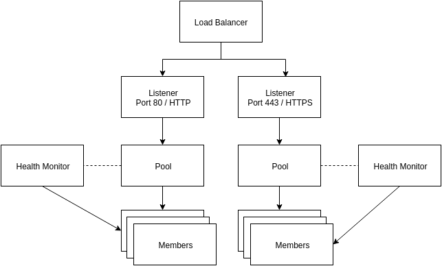
- Load balancer – The load balancer occupies a neutron network port and has an IP address assigned from a subnet.
- Listener – Load balancers can listen for requests on multiple ports. Each one of those ports is specified by a listener.
- Pool – A pool holds a list of members that serve content through the load balancer.
- Member – Members are servers that serve traffic behind a load balancer. Each member is specified by an IP address and port that it uses to serve traffic.
- Health monitor – Members may go offline from time to time and health monitors divert traffic away from members that are not responding. Health monitors are associated with pools.
Single Tenant Deployment
This deployment method has the Avi Controller and Service Engines deployed inside the tenant that provisions the load balancer.
The following illustrates a single tenant mode deployment:
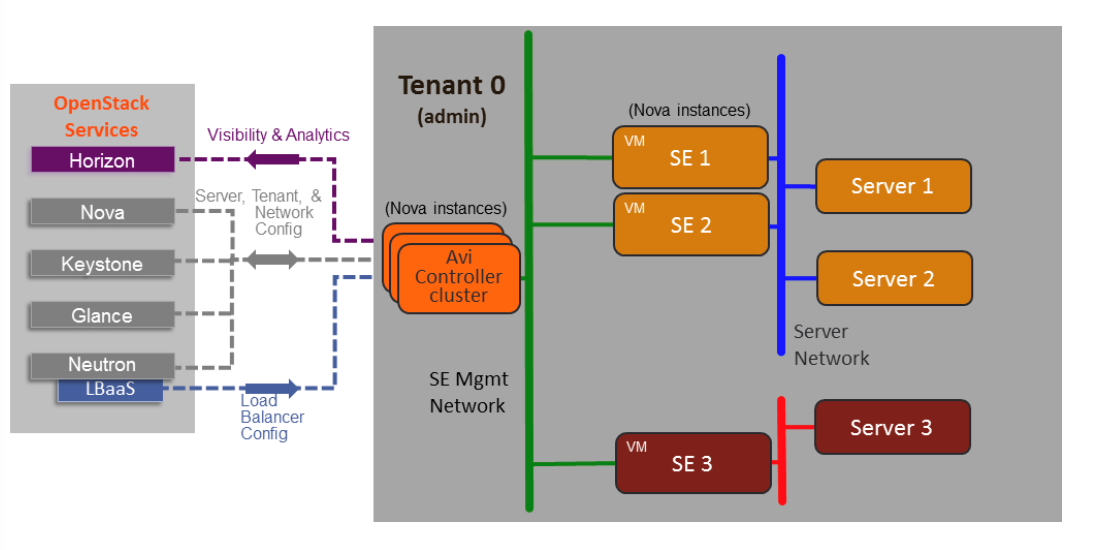
- Avi Controller and Service Engines are deployed on the same tenant.
- Member privileges for the OpenStack tenant are required.
Single Tenant Deployment Flow
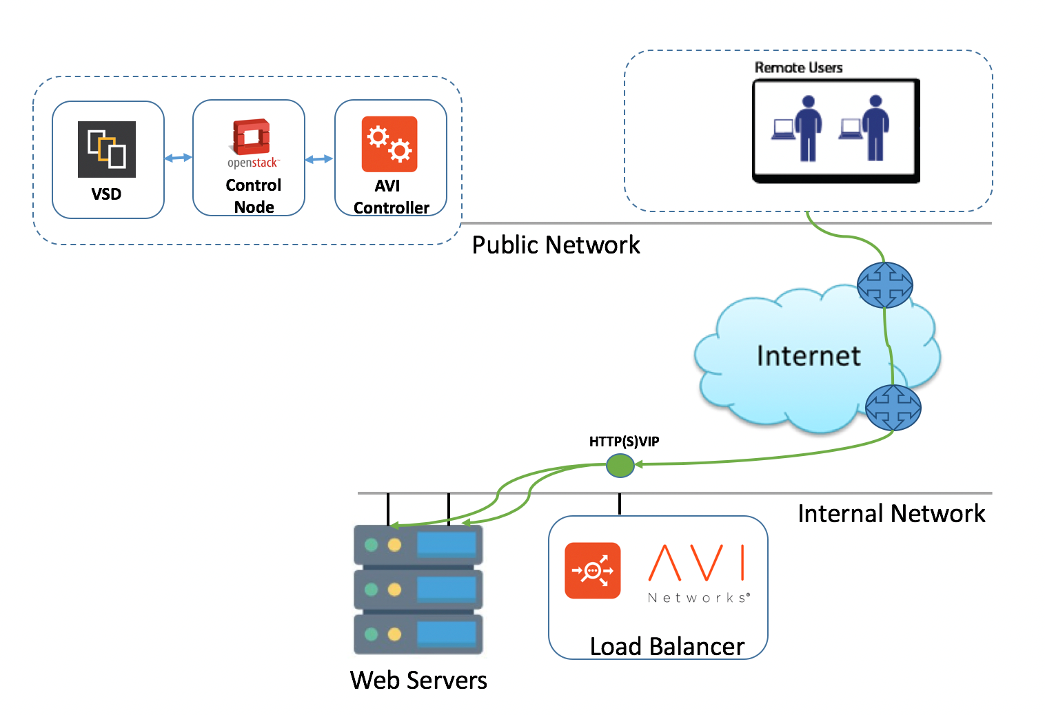
- The administrator provisions a load balancer using Avi Controller web console.
- The Avi Controller triggers the load balancer VM deployment (Service Engine VMs).
- Service Engine exposes the VIP and load balances the traffic to the servers.
Lab Staging
Testing Environment
A single tenant mode described in the previous section will be implemented and tested using the following setup:
- Nuage VSP 5.2.2
- OpenStack Ocata (CentOS)
A typical test lab is as shown in the deployment below:
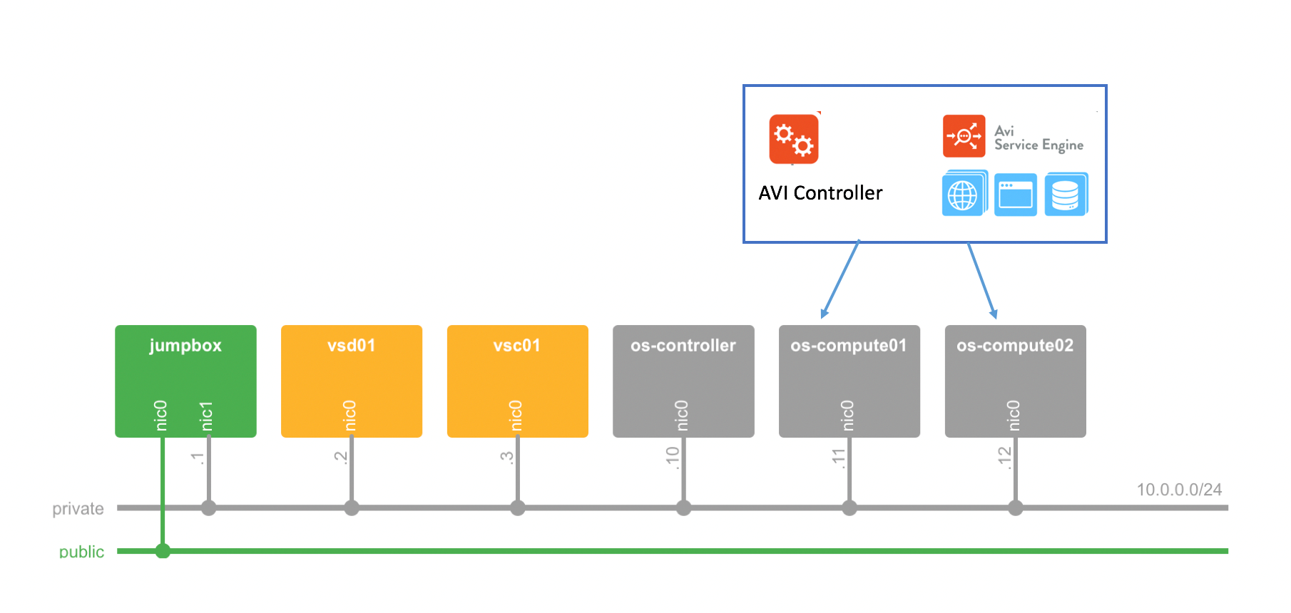
The OpenStack compute nodes that host all components are:
- Avi Controller
- Avi Service Engines
- Web servers (Application servers)
Note:
- If you use NuageX (demo platform) to demonstrate this integration, your lab will have the same topology as shown in the diagram above. Access to individual lab elements is through the jumpbox (that has a single public IP address assigned to its eth0 interface).
- The floating IP network used in the NuageX lab is locally significant. This implies that you are not allowed direct access from the internet. However, it is reachable from the jumpbox. So, you can use iptables on the jumpbox to map precise ports from the floating IP pool to different IPs.
Requirements
- Nuage Networks VSP 5.2.2 with OpenStack Ocata (CentOS)
- Avi Controller 18.1 qcow2 image
- CentOS
Considerations
Multiple integration scenarios such as single or multitenant, simple or HA, Avi managed LBaaS mode, OpenStack managed LBaaS mode, OpenStack or VSD-managed are supported. Each scenario has its own path to implementation. This document discusses the single mode scenario in detail:
The following is a general workflow to deploy Avi Vantage in a single tenant mode that applies to all scenarios:
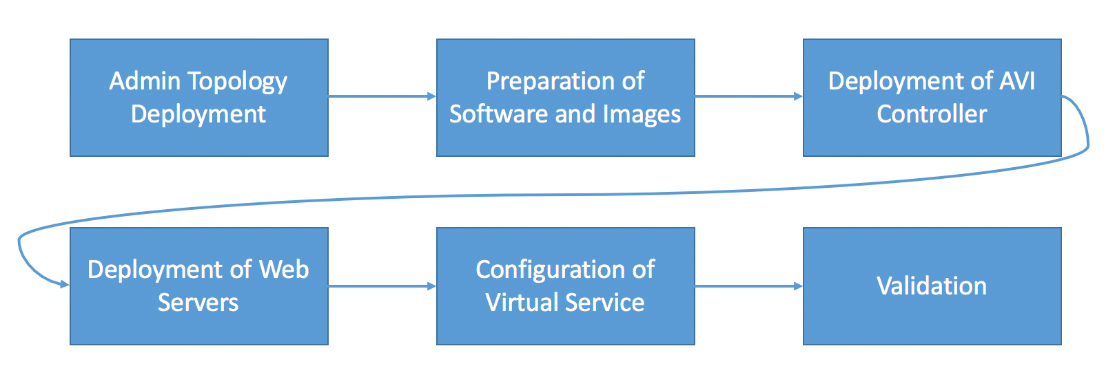
Use a new Nuage networks VSP (5.2.2) in an OpenStack Ocata integrated environment. Follow the steps discussed in the following sections to complete the setup.
Admin Topology Deployment
To deploy Avi Controller and Service Engines, you need to deploy the following network topology in OpenStack.
Standard Single Tenant Mode Scenario
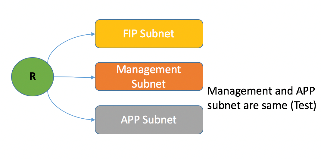
- external_network – Floating IP (external) network. This public IP subnet is needed for external access to the platform (This is a required prerequisite configuration, as per the scenario discussed).
- lab_network – Management network required for deploying the Avi Controller VM. This is the network hosting the client servers. The service engine should have connectivity to
lab_network. (In this lab scenario, Avi Controller VM, Service Engine VMs, and app VMs are connected to the same subnet as the management network. Production scenario should have different subnets).
Follow the steps below to deploy these networks associated with subnets and router:
-
Connect to OpenStack Controller and source the administrator credentials.
Note: Option available on OpenStack GUI as well.
ssh root@10.0.0.10 source keystonerc_admin -
Create the networks and the associated subnets.
neutron net-create lab_network neutron subnet-create --name subnet-mgmt --gateway 10.10.0.1 lab_network 10.10.0.0/24 -
Create the router and connect the networks to it.
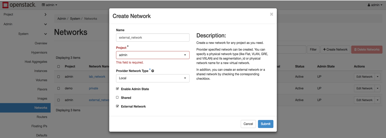
neutron router-create lab_router neutron router-interface-add lab_router subnet-mgmt - Create the external network, also known as, floating IP network (FIP network).
- Navigate to System > Networks
- Click on Create Network
- Provide an external network name
- Select the checkbox for External Network and click on Submit.
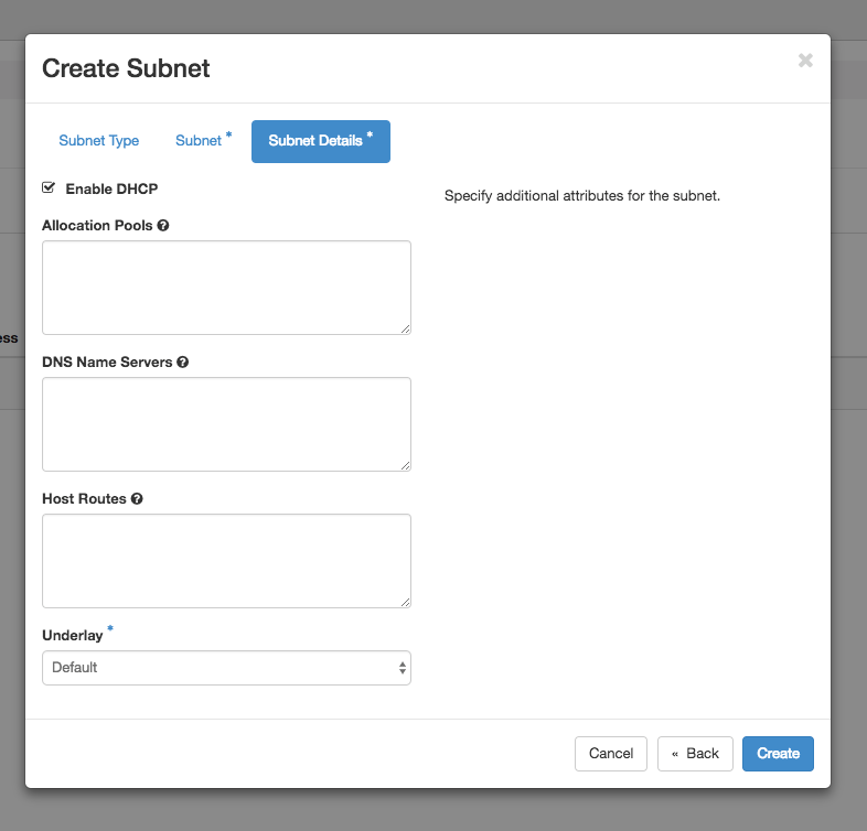
- Create a subnet in the external network.
- Click on the created external network
-
Click on Create Subnet and select the subnet as OpenStack Managed Subnet

- Provide subnet details and click on Next

- Provide any related DHCP options, as required and click on Create.
-
Assign the router gateway as external network (FIP network).
openstack router set lab_router --external-gateway external_network
Preparing Avi Controller Deployment Software
As mentioned in the Requirements section, you need the Avi Controller qcow2 or raw images to create VM or OpenStack cloud. This section explains generating image for Avi Controller using a raw image.
-
Copy the Avi Controller (qcow2) images to the OpenStack Controller in a temp folder and unzip the qcow2 image.
scp controller-18.1.2-9144.qcow2.gz root@10.0.0.10:/tmp/ controller-18.1.2-9144.qcow2.gz -
Create a template using the uploaded image.
glance image-create --name avi_connector_raw --visibility public --disk-format qcow2 --container-format bare < controller-18.1.2-9144.qcow2 -
If not created already, create the flavor for Avi Controller. For this test setup m1.xlarge (8 vCPUs, 16 GB RAM, 160 GB root disk) is used. Following table lists the minimum requirements for deploying the Controller and Service Engines.
It is recommended that the Avi Controller must have eight vCPUs, 24 GB RAM, and minimum 80 GB storage.
Component Memory vCPUs HD Avi Controller 24 GB 8 64 GB Service Engine 2 GB 2 10 GB -
Create the OpenStack flavor using the following command if required.
openstack flavor create –-public m1.avi –-id auto –-ram 256 –-disk 40 –-vcpus 2 --rxtx-factor 1Using the following command to verify all flavors present in the admin tenant.
openstack flavor list
Deploying Avi Controller
This section discusses deploying the Controller and integrating the Controller with the OpenStack Controller and Nuage Networks VSP deployment.
Preparing the Avi Controller Software
The Avi Controller should be assigned an IP address of 10.10.0.6 and connected to the management network lab_network. For this, create a port on the network, spin up the Controller, and connect it to the created port.
-
Create a new port on the OpenStack Controller CLI.
- Get the lab_network and subnet-mgmt IDs
NET_MGMT_ID=$(openstack network list | grep lab_network | awk '{print $2}') SUBNET_MGMT_ID=$(openstack subnet list | grep subnet-mgmt | awk '{print $2}')- Create port with fixed IP for Avi Controller VM
neutron port-create --fixed-ip subnet_id=$SUBNET_MGMT_ID,ip_address=10.10.0.6 $NET_MGMT_ID -
Spin up the Controller VM using the
qcow2image.VDIRECT_PORT_ID=$(neutron port-list | grep 10.10.0.6 | awk '{print $2}') nova boot --flavor m1.large --image avi_connector_raw --nic port-id=$VDIRECT_PORT_ID avi_controller -
Create a floating IP 10.0.1.100 and associate it with the Controller VM.
neutron floatingip-create --floating-ip-address 10.0.1.100 external_network VDIRECT_FIP_ID=$(neutron floatingip-list | grep 10.0.1.100 | awk '{print $2}') neutron floatingip-associate $VDIRECT_FIP_ID $VDIRECT_PORT_ID -
If you are using NuageX https://nuagex.io, then add port-forwarding for Avi Controller IP address on the jumpbox for port 1443 to enable remote access to the Controller.
sudo iptables -t nat -A PREROUTING -i eth0 -p tcp -m tcp --dport 1443 -j DNAT --to-destination 10.0.1.100:443 -
Test Avi Controller GUI access using https://public_lab_ip:1443.

Configuring Avi Controller
The Controller VM needs to be connected to the OpenStack Controller and the Nuage Networks VSP.
-
Access the Controller UI at https://public_ip:8443.
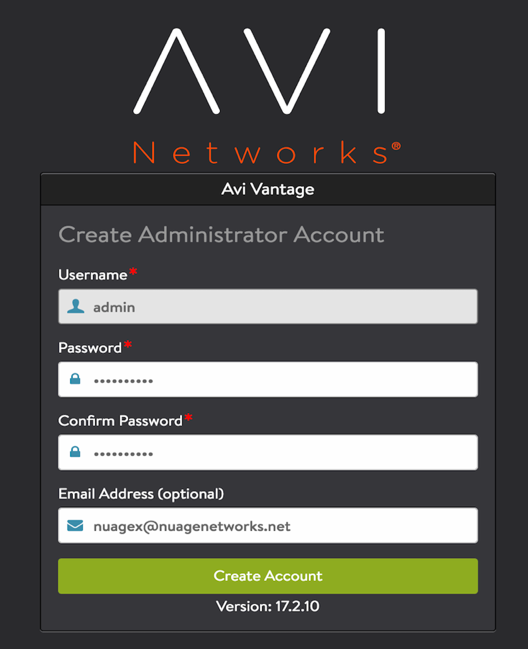
- Provide the following account details:
- username
- password and confirm password
- (Optional) email address that can be used for resetting password
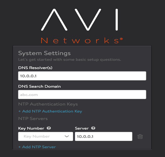
-
Provide the NTP and DNS server details
-
Provide an SMTP server that is used for sending email notifications (No server used in this case).
- No SMTP is used in this lab setup
- Production environment requires an SMTP configuration
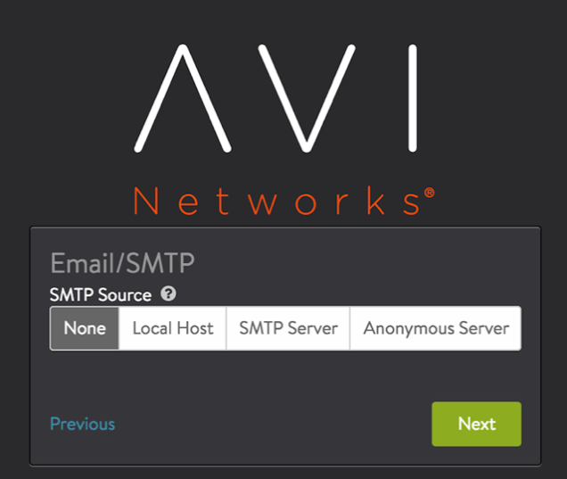
-
Set the infrastructure type as OpenStack.

- Enter the OpenStack cloud settings.
- Provide the tenant user credentials (username/password)
- Provide the keystone auth URL
- Check Use Keystone Auth section and click on Next

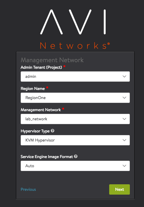
-
Under Management Network, select the admin tenant and choose the management network as lab_network. Select Tenant and Management network as lab_network.
-
Select keystone tenant role mapping as tenant-admin. Select the role as tenant-admin.

-
Select import all tenants from the window, by selecting the checkbox for the following:
a. Import All OpenStack Keystone Tenants
b. Integration with Nuage VSD
Create an user if you are not planning to use the default user as (csproot/csproot/csp) and add that user as a part of the CSP groups.
c. Provide the VSD IP as 10.0.0.2 and port as 443
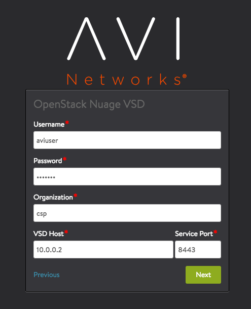
-
Click on Next and navigate to the Controller dashboard UI.
-
Navigate to Infrastructure > Clouds and validate your installation. The status color will change from yellow to green once the Service Engine (image) is pushed to glance.
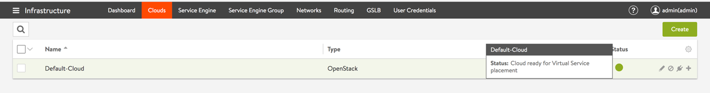
- Verify the license information on the Controller. The license needs to be updated if you are trying to deploy more than two Service Engines.
Deploying Web Servers
Testing load balancing requires several web servers. Download CentOS7 image from the internet. After creating the VMs, configure HTTPD and create a static web page to use.
Spinning up Servers
Download the CentOS image and follow the steps below to spin up two web servers for the demo:
-
Login into the Horizon web interface using administrator credentials.
-
Navigate to Project > Compute > Instances.
-
Click on the Launch Instance button.
-
Provide the following information:
a. Details
i) Instance Name: VM1
ii) Instance Count: 2b. Source
i) Select Boot Source from image
ii) Choose your CentOS-7 imagec. Flavor
i) Select flavor as “m1.small”d. Networks
i) Select lab_network network created in previous sectione. Security Group
i) Select security group to allow the connections throughf. Key Pair
i) Select Key pair which will be used to connect to the CentOS VMs
ii) Choose your public keypair here (This is essential. Without public keypair, you will not be able to login to VMs. Refer to OpenStack Rocky Project User Guides for complete instructions.) -
Click on Launch Instance.
-
Verify that the VMs are created on OpenStack horizon.

After the webserver VMs are deployed, associate the floating IPs to connect directly using SSH. Depending on whether the external_network is OpenStack-managed (single tenant or multitenant scenarios) or VSD-managed (VSD-managed scenario), the workflow to assign floating IPs differs. Refer to the corresponding subsections for complete details on the OpenStack-managed.
OpenStack Managed
If the network is OpenStack-managed, you can use Horizon to assign floating IPs.
-
Navigate to Admin > Floating IPs section on left side of the pane.
-
Click on Allocate IP to Project and select your project as admin from the dropdown and select Allocate Floating IP. Repeat this step to create two floating IPs.
-
Navigate to Project > Compute > Instances.
-
Click on the drop-down menu in front of each VM and select Associate Floating IP:
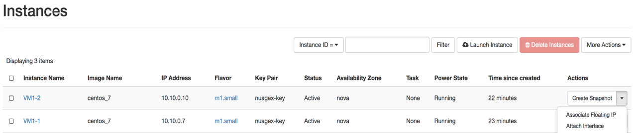
-
In the dialog-box shown, select the IP address and click Associate
-
Repeat steps 1 and 2 for the two other web servers.
In this example, associate 10.0.1.13 and 10.0.1.9 to VM1-1 and VM1-2 respectively.
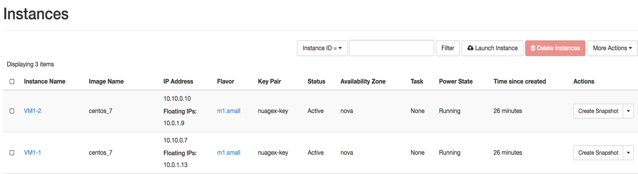
After associating the floating IPs, you should be able to login to the machines using centos user and the public key provided during the deployment. From the jumpbox, ensure that the pub key you added in OpenStack has its private key on the jumpbox to be used.
Installing and Configuring HTTPD
To test load balancing between the three web servers that are deployed in the previous step. Install HTTPD and customize the home pages to show the names of the servers.
-
Connect using SSH to the ws-1 and become root.
ssh centos@10.0.1.9 [centos@ws-1]$ sudo su [root@ws-1 centos]# -
Install EPEL repository
yum install epel-release -
Install HTTPD
yum install httpd -y -
Start and activate httpd at startup
systemctl start httpd systemctl enable httpd -
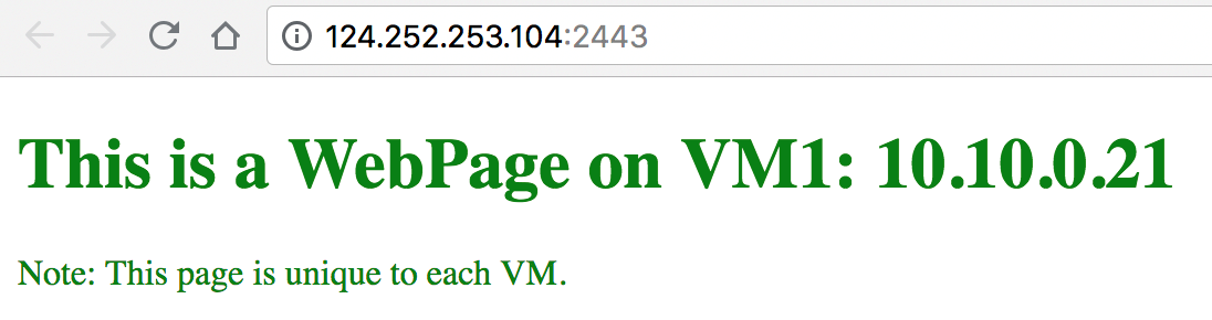
Modify the index.html page to display the server IP in different color for each web server VM (Present in directory
/usr/share/httpd/noindex/) :<!DOCTYPE html>This is a WebPage on VM1: 10.10.0.21
Note: This page is unique to each VM.
-
Restart httpd service using
systemctl restart httpd -
Test web-server locally
[root@vm1 noindex]# curl http://localhost -
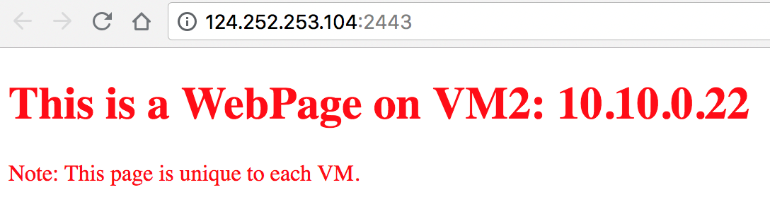
Configure the other web server by repeating steps 1 to 5 with an updated configuration for step 5 as below, which allows reflecting HTML page text in red color.
<!DOCTYPE html>This is a WebPage on VM1: 10.10.0.22
Note: This page is unique to each VM.
Deploying Virtual Service on Avi Controller VM
This section discusses creating a virtual service and validating the setup.
Creating a Virtual Service on Avi Controller
-
Login to Avi Controller UI.
-
Current trial license supports only four Service Engines. Use the configuration below to limit the number of Service Engines:
a. Update Max Number of Service Engines to 2 and save the settings.

-
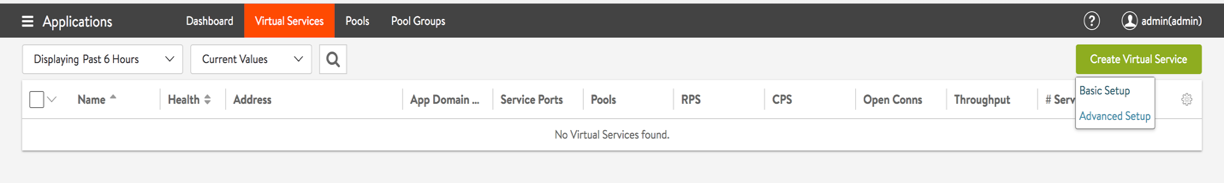
Navigate to Applications > Virtual Services and click on Create Virtual Service.
a. Click on Basic Setup
-
Fill virtual service details as given below:
a. Provide the virtual service name
b. Select the option for Assign Floating IP for External Client Access to assign floating IP to the virtual service
c. As the virtual service will be listening on port 80, enter this value under Service
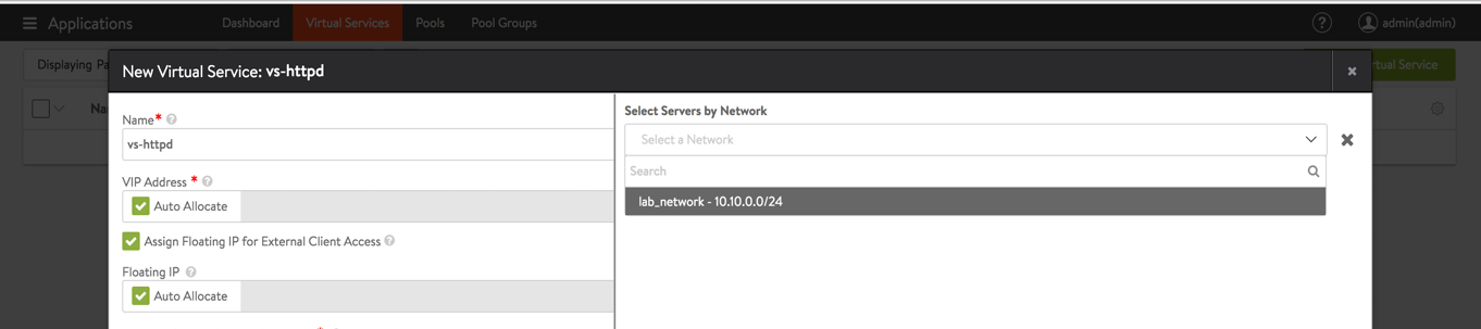
d. Select the Select Servers by Network option to add the web server VMs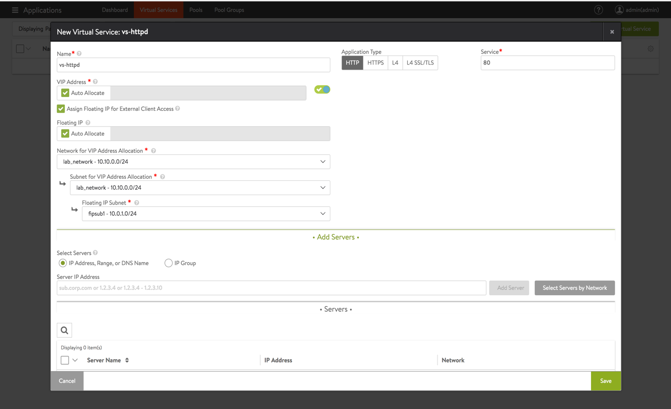
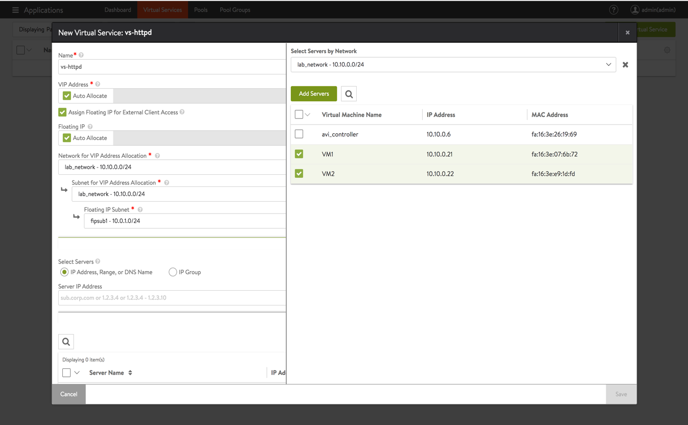
e. Select lab_network where web VMs are present.
f. Select all web servers that were created earlier
-
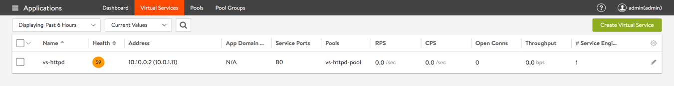
Verify the virtual service created on Avi Controller UI.
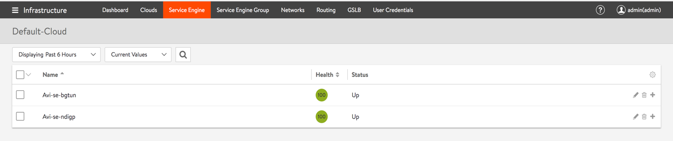
a. Verify the Service Engines that are created by navigating to Infrastructure > Service Engines.
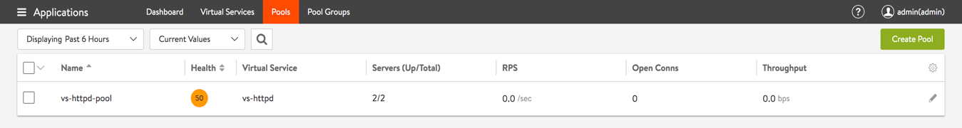
b. Verify that the pool is healthy (In this scenario, health monitor as TCP port 80).
c. Verify virtual service health status by navigating to Applications > Virtual Service.
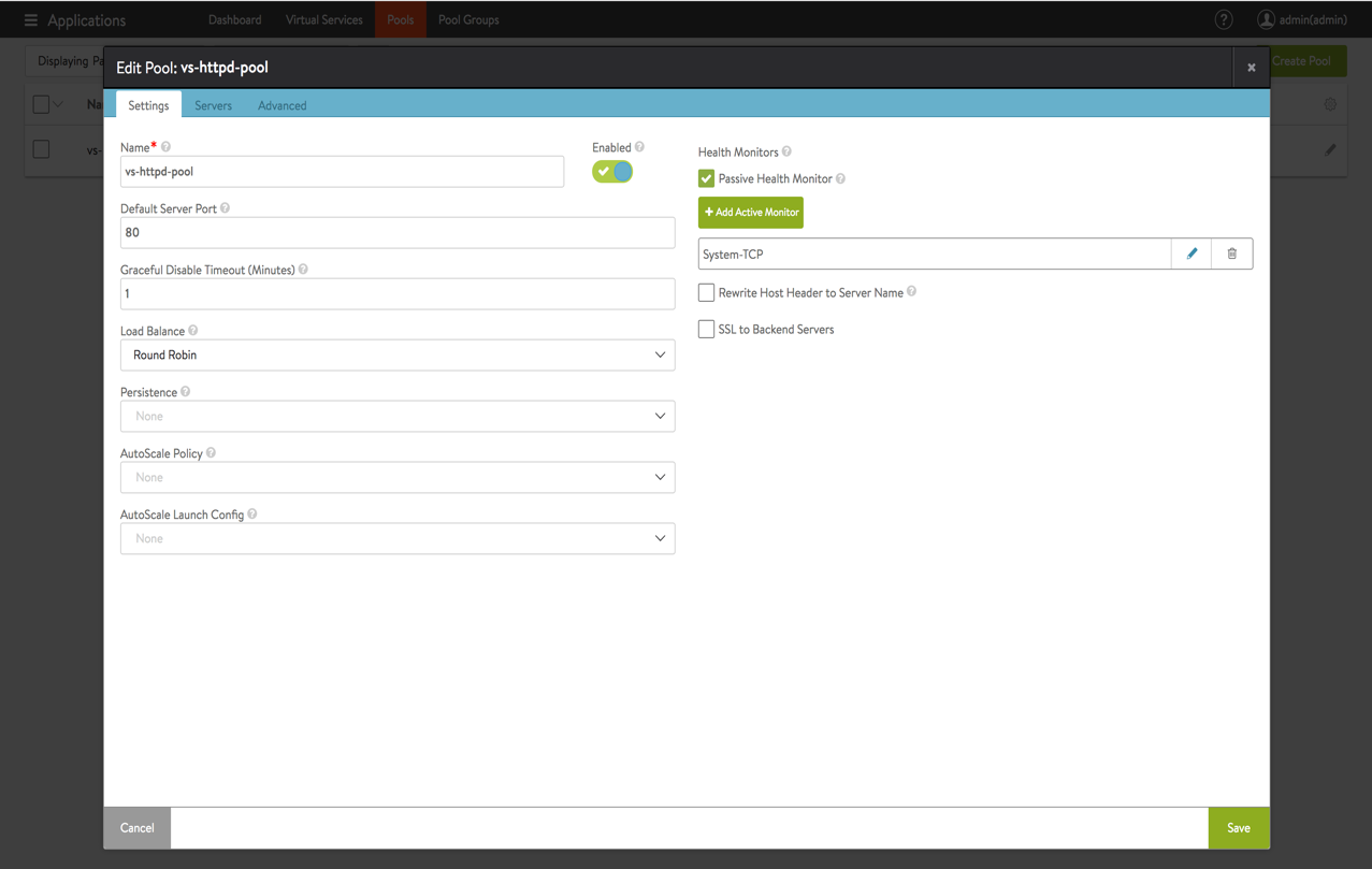
d. Update pool load balancing method as round-robin (which can be updated while creating the virtual service). This can also be configured under Advanced Settings for the virtual service.
-
Since we have assigned a floating IP (note this from the virtual service configuration) to the virtual service, we will create a port forwarding rule for port 2443 on jumpbox which will allow connecting to the virtual service from outside:
a. This configuration is internal to NuageX. If the end user is using NuageX Avi template, the following configuration is required to connect to AVI Controller GUI.sudo iptables -t nat -A PREROUTING -i eth0 -p tcp -m tcp --dport 2443 -j DNAT --to-destination 10.0.1.11:80 -
Connect to virtual service using the configured port forwarding:
a. Connect to virtual service from GUI.
b. Refresh your web browser. A new request should go to another VM.
c. Verify VIP IP and floating IP on Nuage VSD
i) Connect to Nuage VSD of your lab environment.
ii) Navigate to the domain and your VIP port. Verify VIP IP as 10.10.0.6 and floating IP as 10.0.1.11.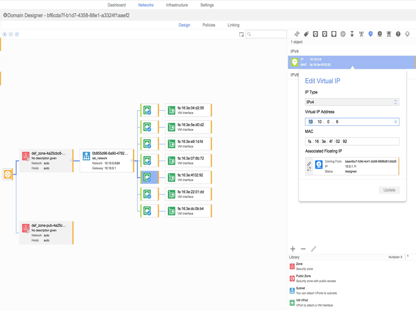
Appendix 1: Creating Security Policy to Allow All in VSD
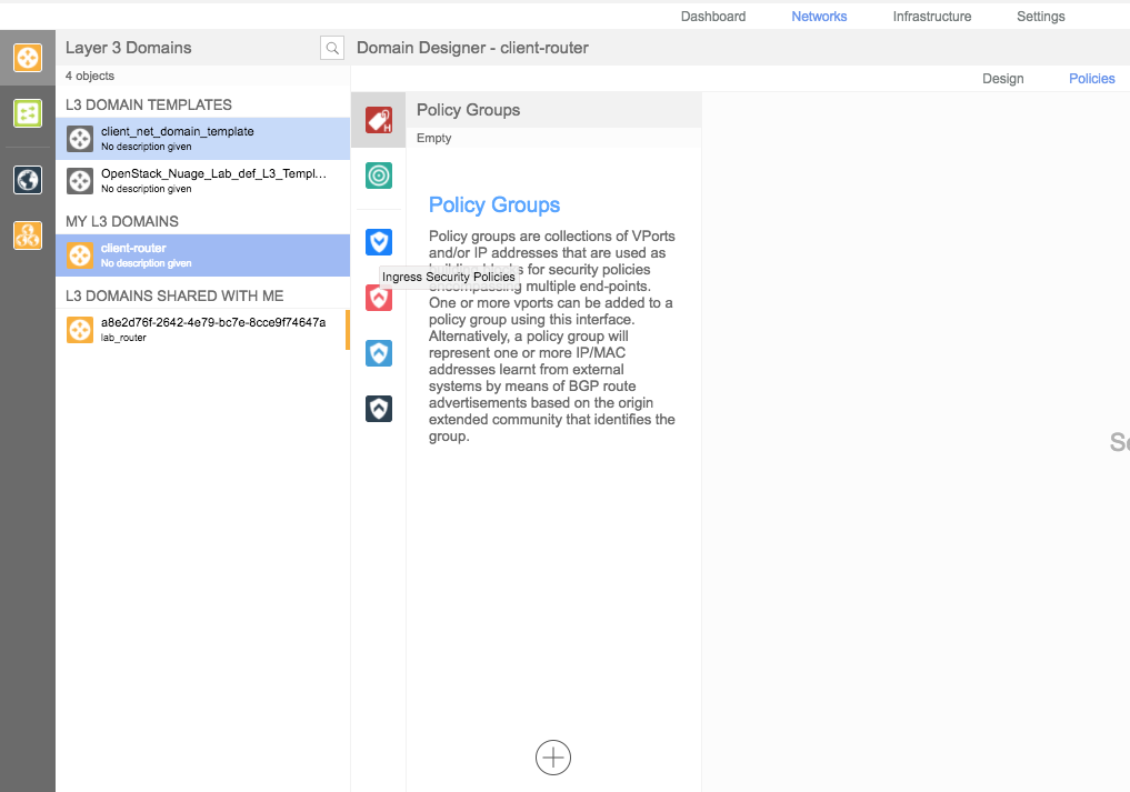
In specific cases (like VSD-managed scenario), after creating the Layer 3 domain in VSD, you need to create a new security policy for the domain to allow traffic (By default, the traffic is denied on creating a new domain).
-
Navigate to Networks > Policies and select the client-router domain:
-
Add ingress and egress ACLs.
-
Click on the Ingress Security Policies icon and create a new rule:
a. Provide a name and check all boxes. This will allow all ingress traffic by default.
b. Click on Create.
-
Repeat the steps for Egress Security Policy.