Route Aggregation for Google Cloud Platform
Overview
This article discusses route aggregation configuration for provisioning a large number of virtual services on an Avi Controller operating in Google Cloud Platform (Cloud Platform).
In this document, Google Cloud Platform, also referred to as Cloud Platform, will be abbreviated as GCP.
Note: Starting with Avi Vantage version 20.1.3, Linux Server Cloud and Avi IPAM on GCP are not supported. For more details on Internal Load Balancer and BYOIP, refer to GCP VIP as Internal Load Balancer and BYOIP.
Route Aggregation
Route aggregation is a method used to minimize the number of route entries required in an IP network. Unlike flat routing, wherein each routing table contains a unique entry for every route, route aggregation consolidates multiple routes into a single route advertisement. The route aggregation feature introduced in Avi Vantage version 17.1 aggregates the /32 routes into mask-based routes to reduce the number of route entries in GCP.
For Avi Vantage deployed in GCP, Avi Controller creates a specific /32 route for each virtual service, so that the incoming traffic is rightly forwarded to the specified virtual service. Depending on the network, the number of virtual services can scale to large numbers and with this the route entries would also increase. However, the number of route entries supported in GCP is limited (about 2000). To address this limitation, the routes that belong to a specific subnet are aggregated to create a mask-route, so that the number of route entries in GCP is reduced.
The steps to configure this feature are discussed in the following sections.
Using Route Integration with Avi Vantage in GCP
To enable aggregation of GCP routes corresponding to multiple virtual services, the virtual IP (VIP) allocated to virtual services should fall within the same subnet range. In case of auto-allocation, the VIP gets allocated from a subnet specified in the Usable Networks of IPAM configuration.
The following are a few examples to demonstrate route aggregation feature:
Example 1: For a single Service Engine.
Without route aggregation:
| Virtual service | Virtual IP | Route programmed in GCP |
| vs1 | 10.1.1.1 | 10.1.1.1/32, next hop=SE1 |
| vs2 | 10.1.1.2 | 10.1.1.2/32, next hop=SE1 |
| vs3 | 10.1.1.3 | 10.1.1.3/32, next hop=SE1 |
| vs4 | 10.1.1.4 | 10.1.1.4/32, next hop=SE1 |
With route aggregation enabled: Note that there is just a single route entry (10.1.1.0/29) in GCP.
| Virtual service | Virtual IP | Route programmed in GCP |
| vs1 | 10.1.1.1 | 10.1.1.0/29, next hop=SE1 |
| vs2 | 10.1.1.2 | |
| vs3 | 10.1.1.3 | |
| vs4 | 10.1.1.4 |
As there is a single aggregated route programmed for multiple virtual services, these virtual services need to be part of the same Service Engine group, so that the next hop which is the Service Engine for these virtual services can be the same.
Example 2: Virtual service scaled out to two Service Engines within a SE group.
Without route aggregation:
| Virtual service | Virtual IP | Route programmed in GCP |
| vs1 | 10.1.1.1 | 10.1.1.1/32, next hop=SE1 10.1.1.1/32, next hop=SE2 |
| vs2 | 10.1.1.2 | 10.1.1.2/32, next hop=SE1 10.1.1.2/32, next hop=SE2 |
| vs3 | 10.1.1.3 | 10.1.1.3/32, next hop=SE1 10.1.1.3/32, next hop=SE2 |
| vs4 | 10.1.1.4 | 10.1.1.4/32, next hop=SE1 10.1.1.4/32, next hop=SE2 |
With route aggregation enabled:
| Virtual service | Virtual IP | Route programmed in GCP |
| vs1 | 10.1.1.1 | 10.1.1.0/29, next hop=SE1 10.1.1.0/29, next hop=SE2 |
| vs2 | 10.1.1.2 | |
| vs3 | 10.1.1.3 | |
| vs4 | 10.1.1.4 |
The subnet mask used for aggregating the route should be configured as a part of the SE group using service_ip_subnet configuration option, as explained later. This subnet should be derived from one of the Usable Networks configured in the Avi IPAM, from which the VIP is allocated.
Example 3: Virtual services scaled out to multiple SE groups.
While configuring a large number of virtual services, the limit of virtual services per SE may hit the maximum, based on the size of the Service Engine. In order to overcome this, virtual services will need to be distributed across multiple SE groups, so that the groups of virtual services within each SE group can be aggregated through route aggregation.
On enabling route aggregation and configuring service_ip_subnet for individual SE groups, Avi Controller automatically places the virtual service to one of the SE group, while the VIP for the virtual services gets allocated from within the service_ip_subnet configured on that SE group.
Consider an instance with eight virtual services. Based on the expected throughput and the size of selected SE VM, the maximum number of virtual services per SE needs to be restricted to two. To configure eight virtual services, four SE groups will have to be created. Each SE group will program two aggregated routes (two SEs in each SE group). Thus, four subnets will need to be configured. This needs to be carved out from the larger IPAM subnet.
Calculation Details:
The following are the calculation details:
- Configured Avi IPAM subnet = 10.1.1.0/24
- Configured maximum number of virtual service per SE = 2
- Maximum number of virtual services expected = 8
- Number of SE groups required = 8/2 = 4
- Number of service_ip_subnets to be configured = 4
The IPAM subnet 10.1.1.0/24 needs to be divided into four subnets, and each should be assigned to one SE group as follows:
| Virtual service | SE group | service_ip_subnet | Virtual IP | Route programmed in GCP |
| vs1 | SE Group 1 | 10.1.1.0/26 | 10.1.1.1 | 10.1.1.0/26, next hop = SE1 10.1.1.0/26, next hop = SE2 |
| vs2 | SE Group 1 | 10.1.1.0/26 | 10.1.1.2 | |
| vs3 | SE Group 2 | 10.1.1.64/26 | 10.1.1.65 | 10.1.1.64/26, next hop = SE3 10.1.1.64/26, next hop = SE4 |
| vs4 | SE Group 2 | 10.1.1.64/26 | 10.1.1.66 | |
| vs5 | SE Group 3 | 10.1.1.128/26 | 10.1.1.129 | 10.1.1.128/26, next hop = SE5 10.1.1.128/26, next hop = SE6 |
| vs6 | SE Group 3 | 10.1.1.128/26 | 10.1.1.130 | |
| vs7 | SE Group 4 | 10.1.1.192/26 | 10.1.1.193 | 10.1.1.192/26, next hop = SE7 10.1.1.192/26, next hop = SE8 |
| vs8 | SE Group 4 | 10.1.1.192/26 | 10.1.1.194 |
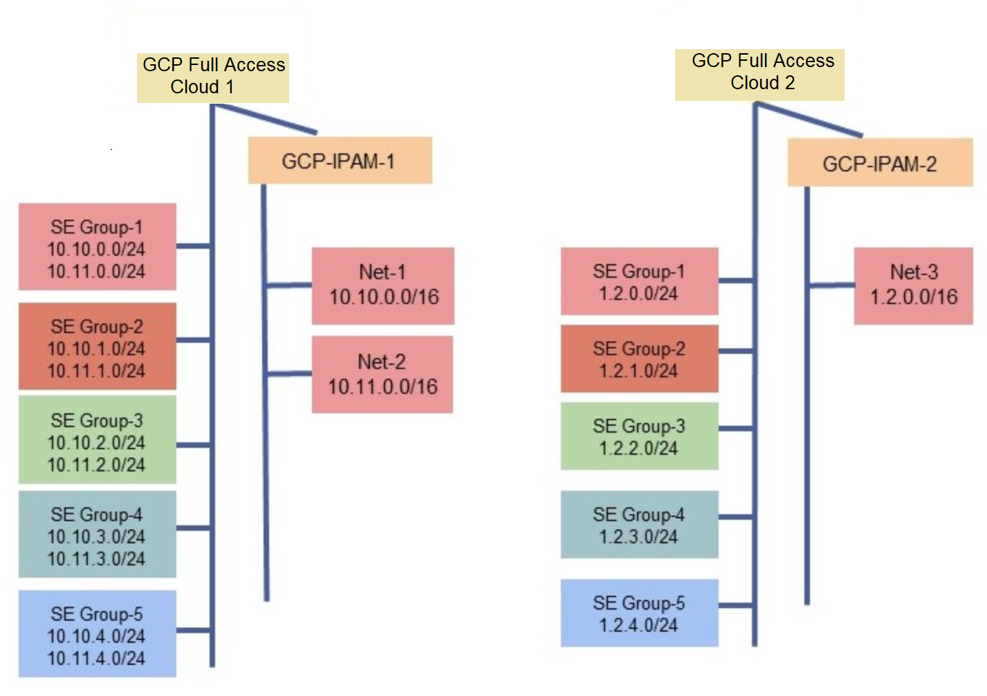
Example 4: Multiple clouds and IPAM subnets.
The figure below depicts a complex configuration setup which would follow the same principle of route aggregation.
Configuration Steps
This article assumes that the Avi Vantage Controller, SEs, cloud, IPAM, and networks have been set up as per Avi Deployment Guide for Google Cloud Platform. Ensure all steps in the document have been completed before proceeding with the following steps for configuring route aggregation:
Step 1 — Enable the match_se_group_subnet field in GCP cloud.
The following is the CLI command to enable route aggregation in GCP cloud using the CLI:
[admin:<ctrl_ip>]: > configure cloud gcp_cloud
[admin:<ctrl_ip>]: cloud> gcp_configuration
[admin:<ctrl_ip>]: cloud:gcp_configuration> vip_allocation_strategy
[admin:<<ctrl_ip>]: cloud:gcp_configuration:vip_allocation_strategy> mode routes
[admin:<ctrl_ip>]: cloud:gcp_configuration:vip_allocation_strategy> routes
[admin:<<ctrl_ip>]: cloud:gcp_configuration:vip_allocation_strategy:routes> match_se_group_subnet
[admin:<ctrl_ip>]: cloud:gcp_configuration:vip_allocation_strategy:routes> save
[admin:<ctrl_ip>]: cloud:gcp_configuration:vip_allocation_strategy> save
Step 2 — Plan the number of SEs and SE groups required.
The minimum number of SE groups required can be calculated as follows:
- Estimate the total number of virtual services to be provisioned. Call that V.
- The maximum number of virtual services a single SE can host will be called M. For more information, refer to CPU Memory Allocations.
- The total number of SE groups will be V/M; let that be represented by N.
- Divide the IPAM network into N smaller subnets, such that each subnet has a maximum of M IP addresses. The Avi Controller uses these subnets to program the routes in GCP, instead of individual /32 routes corresponding to each VIP and SE(s) on which the VIP is placed.
The following are a few examples for the above mentioned calculation:
Example 1:
(i) The total number of virtual services to be provisioned is 256.
(ii) The maximum number of virtual services that can be hosted on a single SE is 64.
(iii) Therefore, the number of SE groups needing to be created is 256/64 = 4.
(iv) The IPAM network created for virtual service is 10.10.0.0/24, which has 254 IP addresses.
(v) Divide the IPAM network into four smaller subnets of 64 IP addresses each: 10.10.0.0/26, 10.10.0.64/26, 10.10.0.128/26 and 10.10.0.192/26.
Example 2:
(i) The total number of virtual services to be provisioned is 512.
(ii) The maximum number of virtual services that can be hosted on a single SE is 32.
(iii) Therefore, the number of SE groups needing to be created is 512/32 = 16.
(iv) The IPAM network created for virtual service is 10.10.0.0/23, which has 510 IP addresses.
(v) Divide the IPAM network into 16 smaller subnets of 32 IP addresses each: 10.10.0.0/27, 10.10.0.32/27, 10.10.0.64/27 till 10.10.1.224/27.
Step 3: Set up SE groups.
(i) Starting with Avi Vantage version 17.2, all SE group HA modes are supported. Prior to this version, if the route aggregation feature is enabled, then the high availability (HA) mode should be set to active/active. The other HA modes, such as N+M buffer or active/standby mode are not supported.
(ii) Configure service-IP subnets for each SE group. Service-IP subnets will provide IP addresses to the respective virtual services in their respective SE group. For this, configure a service-IP subnet object in the SE group configuration. The service-IP subnet should be set to smaller subnets, calculated as shown in Step 2(iv). This field can only be set via the CLI.
Note: Once the field service-IP subnet is used, virtual service IPs are allocated only from the specified SE group. If the subnet is not set, then you must program a /32 route for the virtual service IPs.
(iii) Configure min_scaleout_per_vs and max_scaleout_per_vs values to the number of SEs in the SE group as determined in Step 2 Example 1 (ii).
(iv) Configure max_vs_per_se value to the maximum number of virtual services that a single SE can host (64 in this case) as determined in Step 2 Example 1 (ii).
[admin:10-146-14-2]: > configure serviceenginegroup gcp-route-aggregation
[admin:10-146-14-2]: serviceenginegroup> ha_mode ha_mode_shared_pair
[admin:10-146-14-2]: serviceenginegroup> max_vs_per_se 64
[admin:10-146-14-2]: serviceenginegroup> min_scaleout_per_vs 2
[admin:10-146-14-2]: serviceenginegroup> max_scaleout_per_vs 2
[admin:10-146-14-2]: serviceenginegroup> service_ip_subnets 10.10.0.0/26
[admin:10-146-14-2]: serviceenginegroup> save
+---------------------------------------+---------------------------------------------------------+
| Field                                 | Value                                                   |
+---------------------------------------+---------------------------------------------------------+
| uuid                                  | serviceenginegroup-fbd33752-996d-48aa-9534-08372ef10095 |
| name                                  | gcp-route-aggregation                                   |
| max_vs_per_se                         | 64                                                      |
| min_scaleout_per_vs                   | 2                                                       |
| max_scaleout_per_vs                   | 2                                                       |
………
| ha_mode                               | HA_MODE_SHARED_PAIR                                     |
……….
| service_ip_subnets[1]                 | 10.10.0.0/27                                            |
………..
+---------------------------------------+---------------------------------------------------------+
Note: All SE groups in a cloud should have similar configuration. Only the service-IP subnets will be different for each SE group.
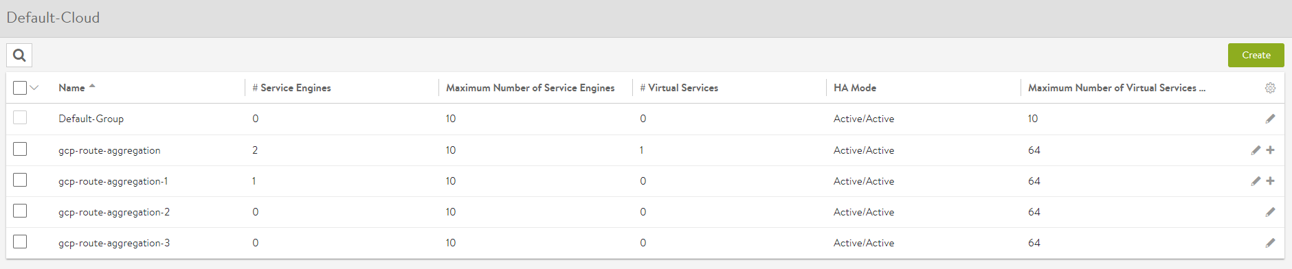
Figure 3: Creating Service Engine Groups
Step 4: Add SEs to the SE groups
The number of SEs in each SE group should be equal to max_scaleout_per_vs value as discussed in Step 3 (iv).
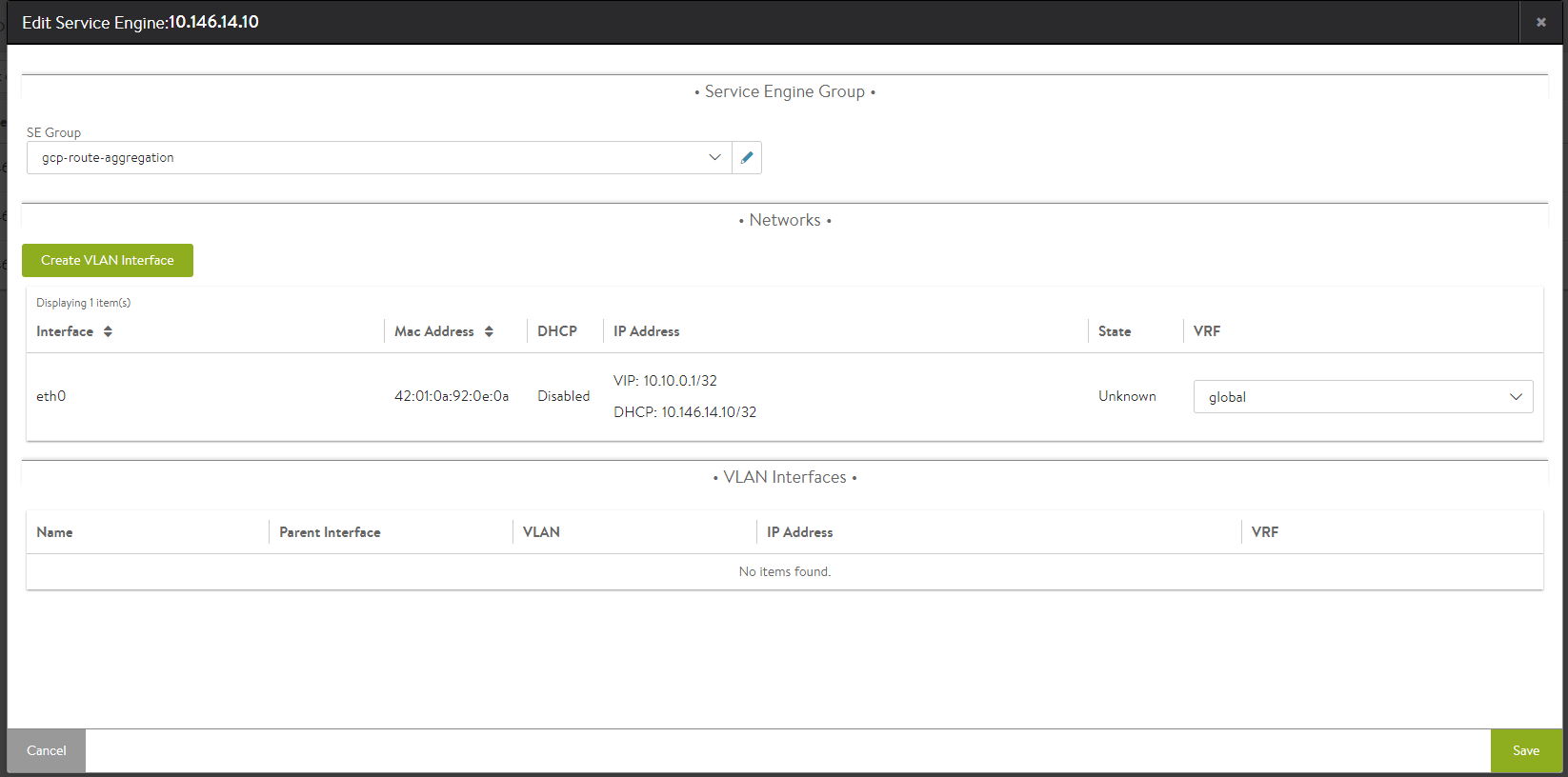
Figure 4: Adding the requisite SE to the respective SE group
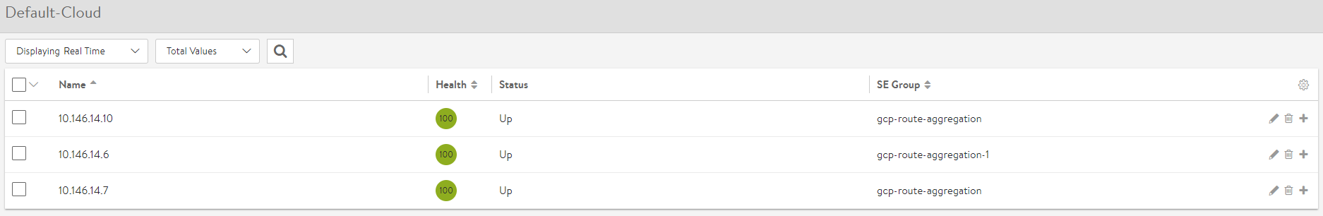
Figure 5. SEs reflecting the respective SE group
Step 5: Create a virtual service
Create a virtual service using auto-allocation, as explained in Avi Deployment Guide for Google Cloud Platform. Note that all virtual services should use auto-allocation with this feature. The SE group is automatically selected by the Avi Controller to distribute virtual services across different SE groups. Any manual SE-group selection will be overridden by the IPAM, based on the auto-allocated VIP. For more information on virtual service placement, refer to Virtual Service Placement Policy..
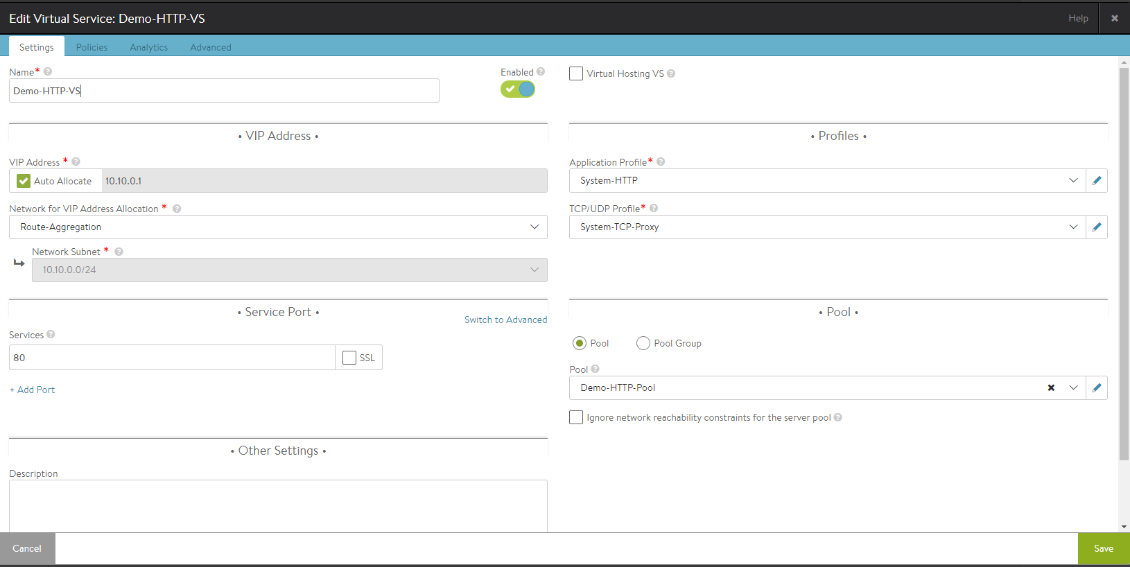
Figure 6: Creating Virtual Service using the created IPAM Profile

Figure 7: Aggregated Routes
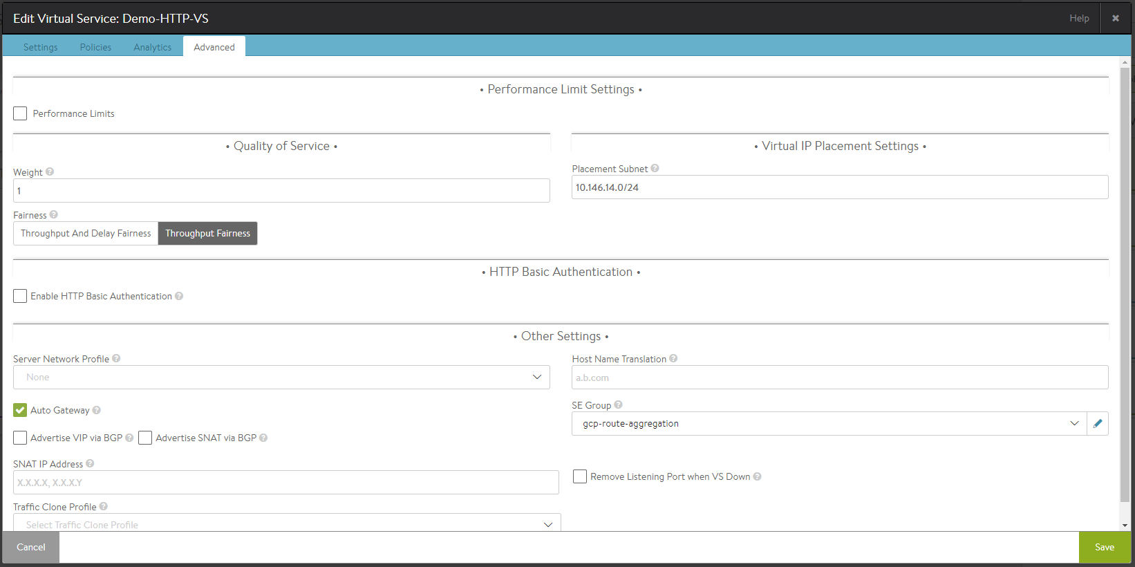
Figure 8: Post Virtual Service Creation: SE group is automatically updated under Advanced Settings
Troubleshooting
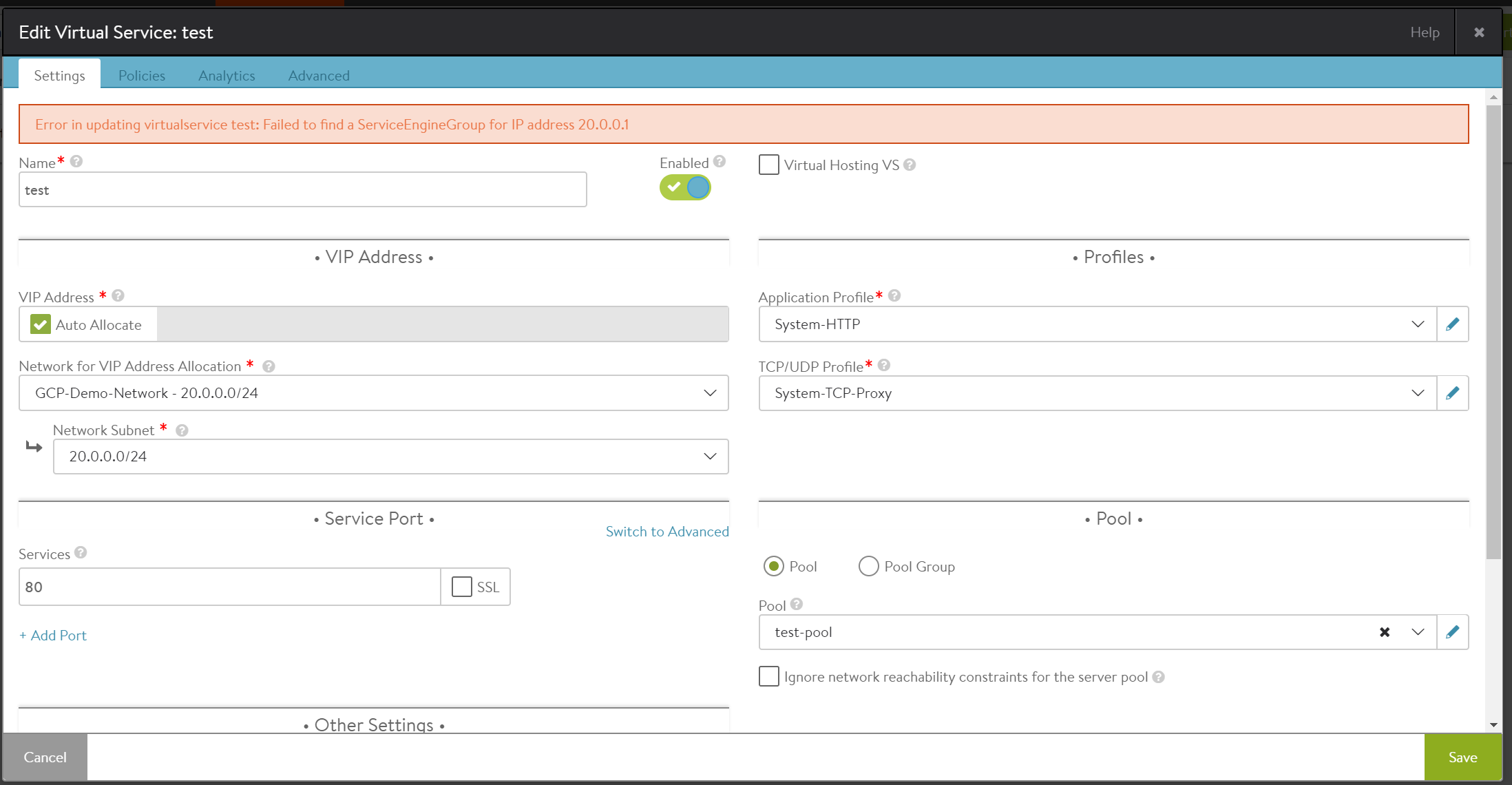
Scenario 1: Selecting different IPAM profile
As explained in Step 3 (iv), the service_ip_subnet field should be configured for an SE group that will match the respective IPAM profile. If a different IPAM profile is chosen, the following error will result:
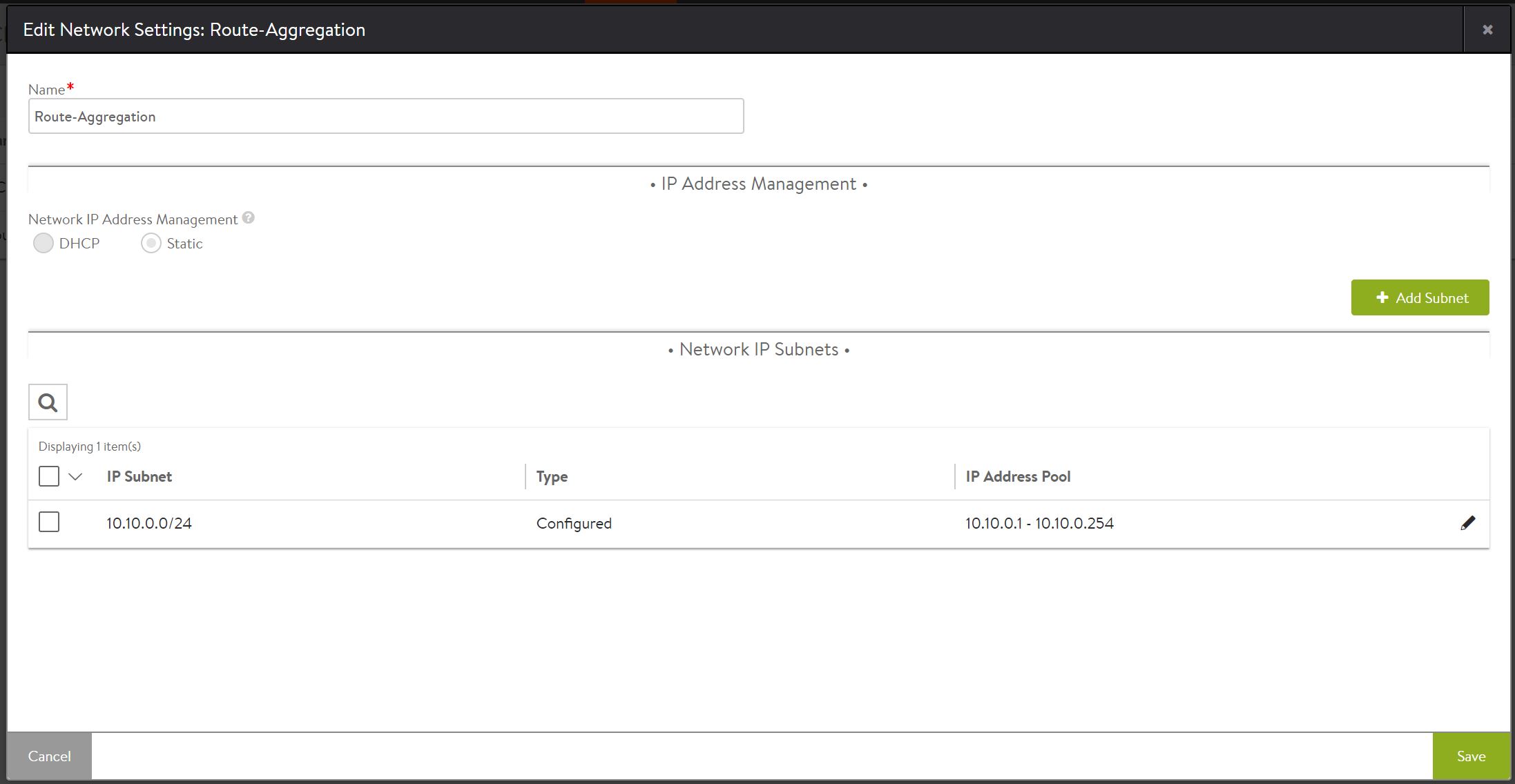
Scenario 2: Static IP address pool not configured
Under network settings, if a static IP address pool has not been configured for an IP subnet, the following error will result.
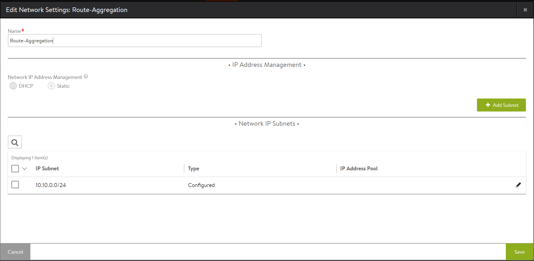
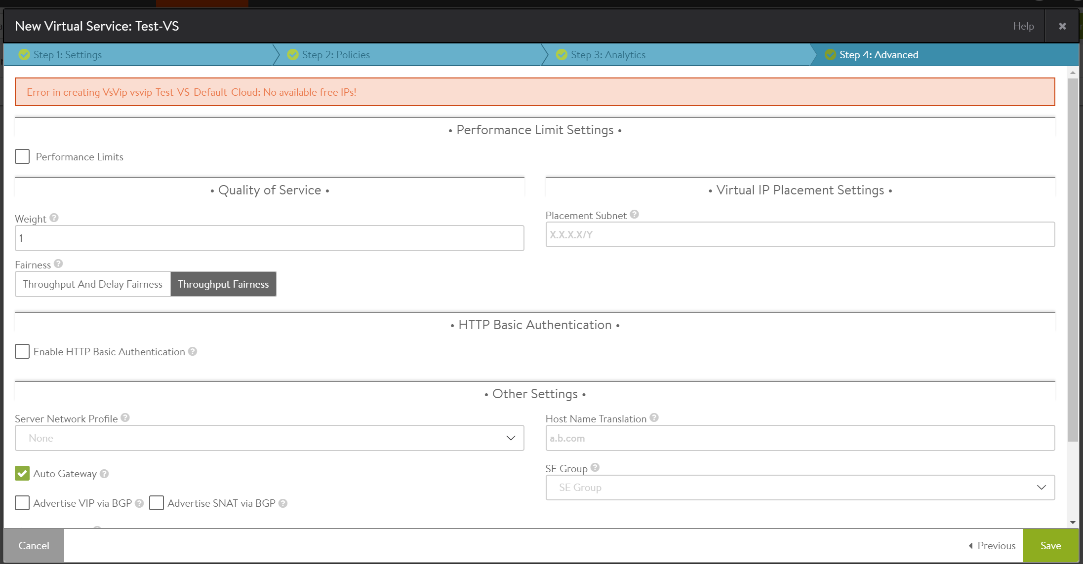
You can fix this by choosing a static range, as displayed in earlier examples.