Avi GSLB Solution for Active/ Active Deployments for UAG
Overview
Global Server Load Balancing (GSLB) is the act of balancing an application’s load across instances of the application that have been deployed to multiple locations. Application load at any one of those locations is usually managed by a local load balancer.
With companies and employees alike preferring to work from home or work on the go, there really is no guarantee where users may be at any point in time. This presents a headache to most companies as they plan to create front doors for user productivity. The challenge is much larger than just availability, disaster recovery, or business continuity today than it was a couple of years ago.
The go-to solution for this is Global Server Load Balancing. With GSLB, access to resources is controlled with DNS queries and health checking. Knowing if a site is healthy or not, GSLB serves back the IP in the form of a DNS record of the site the user should access based on the configured logic.
If you have multiple instances of application/UAG servers deployed across the globe, and your users are geographically dispersed then, GSLB is required.
Prerequisites
Ensure the following prerequisites are met:
-
Avi Controllers are set up in all the data centers
-
Avi cloud configuration is complete
-
Avi sites are added in GSLB and DNS VS are configured on the individual sites as per the requirement
-
UAG servers configured as per requirements along with other Horizon components
-
DNS entries as shown here
Reference Architecture
Avi Vantage can be deployed on on-prem or on any cloud ecosystem which allows for easy deployment to load balance Horizon traffic in any ecosystem.
Avi GSLB enables distributing the load across multiple, geographically dispersed data centers.
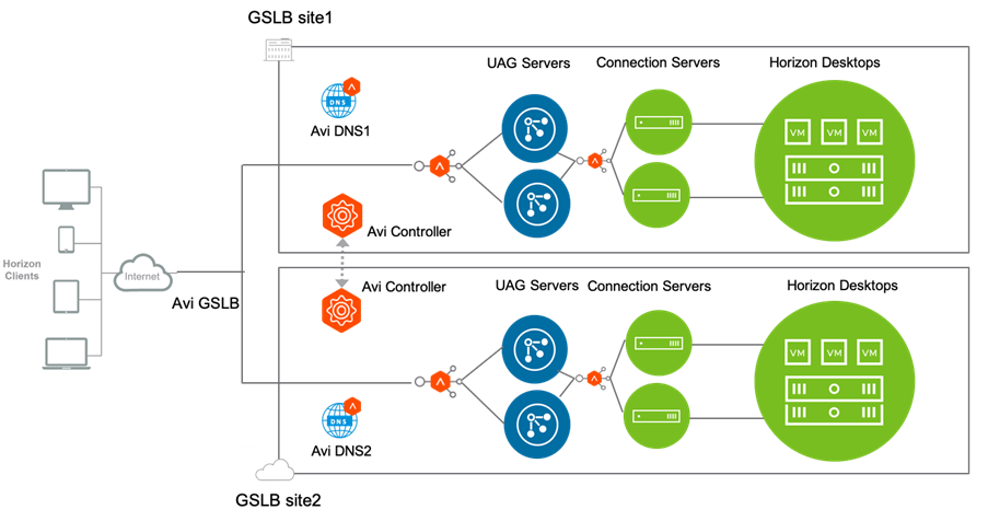
Only two GSLB sites are shown here. You can add more GSLB sites as per the requirement.
Consider the request flow with the sample topology:
- Avi is running in two locations (GSLB sites):
- On-premises (Avi GSLB Site 1)
- Public Cloud (Avi GSLB Site 2)
Each site has its own Avi Controller Cluster (represented by a single Controller icon)
- The Avi load balancer for UAG has virtual services running in Avi GSLB Site 1 and Avi GSLB Site 2 respectively:
- uagvip.site1.com
- uagvip.site2.com
-
Avi GSLB Site 1 and Avi GSLB Site 2 have global DNS services (Avi DNS1, Avi DNS2 respectively). They are equally authoritative for the subdomain appshzn.com.
-
Avi monitors the health of the virtual services to choose the best location (that is, rule out unhealthy locations)
- It synchronizes configuration and state across GSLB sites, to ensure VS1 and VS2 can continue despite certain failures
Note: The IP and FQDN used in the example are for illustration purposes only. Replace this with your real environment details.
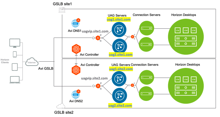
The GSLB service (GS) app domain name is demo.appshzn.com. The DNS entries to be made are as follows:
For Site 1:
| FQDN | Entity Description | IP address – used for DNS entries | Real IP |
|---|---|---|---|
| uagvip.site1.com | FQDN of Avi LB VIP | VIP1 | 10.10.5.200 |
| uag1.site1.com | FQDN of Uag server1 on site 1 | VIP1 | 10.58.17.163 |
| uag2.site1.com | FQDN of uag server 2 on site 1 | VIP1 | 10.58.17.164 |
For Site 2:
| FQDN | Entity Description | IP address – used for DNS entries | Real IP |
|---|---|---|---|
| uagvip.site2.com | FQDN of Avi LB VIP | VIP2 | 10.10.10.100 |
| uag1.site2.com | FQDN of UAG server1 on site 2 | VIP2 | 10.98.17.163 |
| uag2.site2.com | FQDN of uag server 2 on site 2 | VIP2 | 10.98.17.164 |
Note: If there are more than 2 UAG servers then we need to add the host entry/DNS entry for all the UAG servers.
Request Flow
The request flow for this deployment is as shown below:
-
User sends a request to access demo.appshzn.com over the internet.
-
The request goes to the Corporate DNS server that further sends the DNS query to one of the two Avi DNS servers: Avi DNS 1 or Avi DNS 2.
-
Assume that the request goes to Avi DNS 1. Avi DNS 1 selects the UAG VIP depending on the GSLB algorithm.
-
Assume that Avi DNS responds to the client with the IP address of Site 2 VIP (uagvip.site2.com).
-
Now the client sends a request directly to Avi LB on site 2 (uagvip.site2.com).
-
The Avi load balancer does the load balancing and sends the request to one of the backend UAG servers. In this case, Avi sent the request to UAG server 1 on site 2 (uag1.site2.com).
-
UAG sends 307 redirect to client with uag1.site2.com FQDN.
-
Client looks for location header and queries the host in the location header (uag1.site2.com ).
-
Due to the DNS entries that were created (shown in the tables above), the FQDN (uag1.site2.com) will be resolved to Avi VIP IP ie VIP2.
-
Client starts authentication with new UAG FQDN (uag1.site2.com). From the 307 redirect, all further flows will have the host header set.
-
When the request comes to the Avi LB, the Avi virtual service parses the host header and forwards to UAG based on the host header (FQDN uag1.site2.com ) using the HTTP policies.
-
UAG1.site2.com performs authentication, verifies entitlements and returns the secondary protocol information of blast IP uagvip.site2.com or VIP IP ( PCoIP) with configured blast Port on UAG i.e. 4001.
-
Client request comes to the L4 virtual service. The L4 virtual service uses a DataScript to send the request to correct UAG server based on the incoming destination port.
Configurations for Load Balancing
The configuration steps for load balancing UAG are as below:
- Creating Custom Health Monitor for UAG
- Creating Pools
- Creating SSL Profile and Install SSL Certificate
- Creating an L7 Virtual Service and HTTP request policies
- Creating an L4 Virtual Service using the L7 virtual service as shared VIP and specify all the ports required for secondary protocols
- Creating an L4 DataScript
Follow the steps given below to configure the Site 1:
Creating Custom Health Monitor for UAG
To create a custom health monitor,
- From the Avi UI, navigate to Templates > Profiles > Health Monitors.
- Click on Create.
- Select the vCenter cloud that was created for Horizon.
- Enter the following details in the New Health Monitor screen.
Field Value Send Interval 30 Receive Timeout 10 Client Requested Data GET /favicon.ico HTTP/1.0 Response Code 2xx The New Health Monitor screen is as shown below:
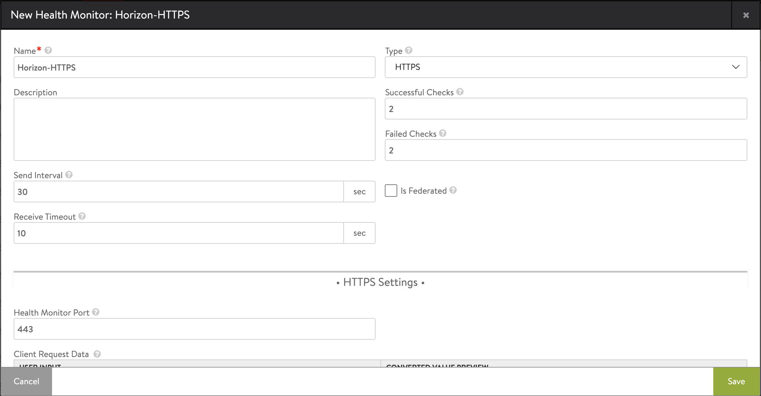
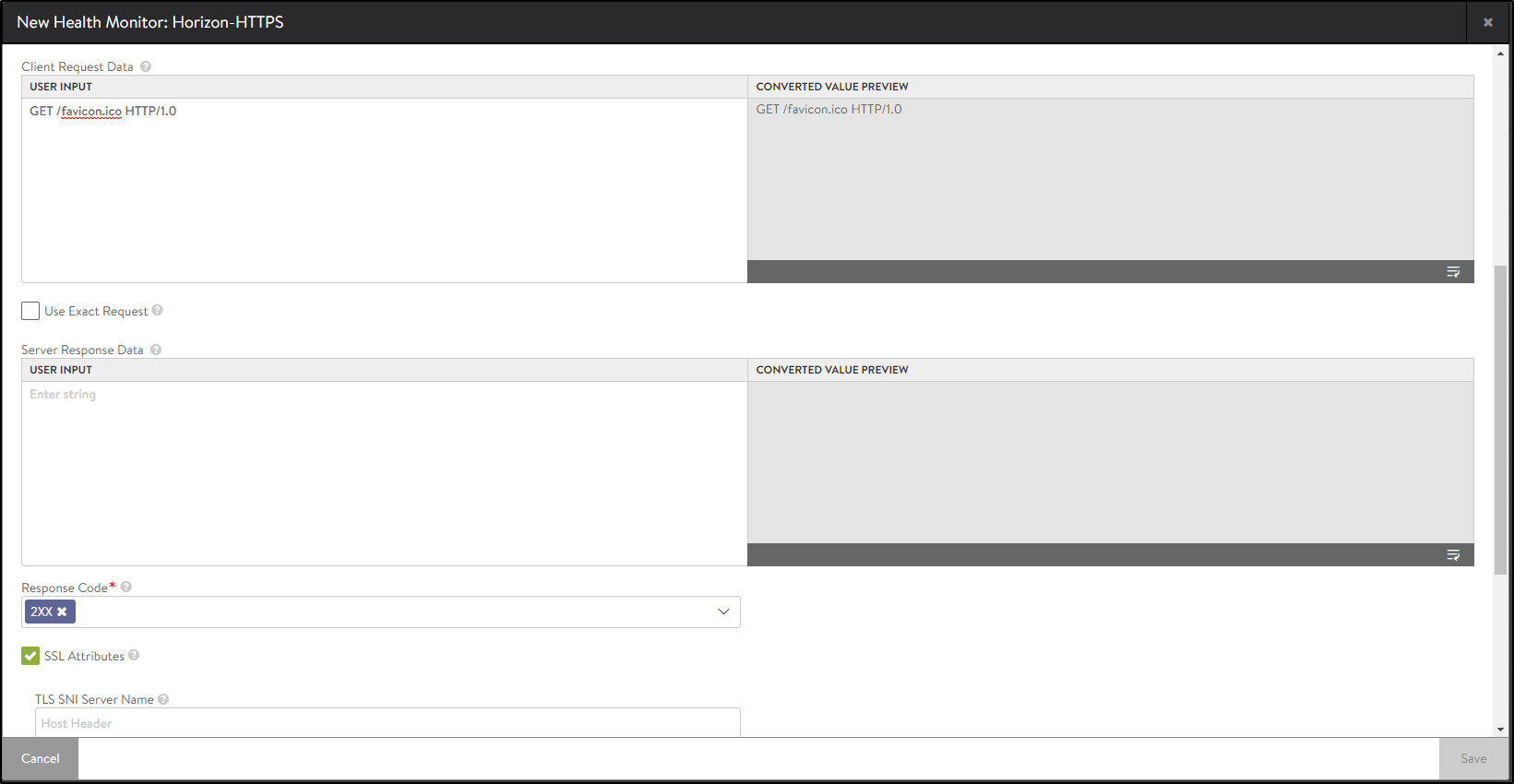
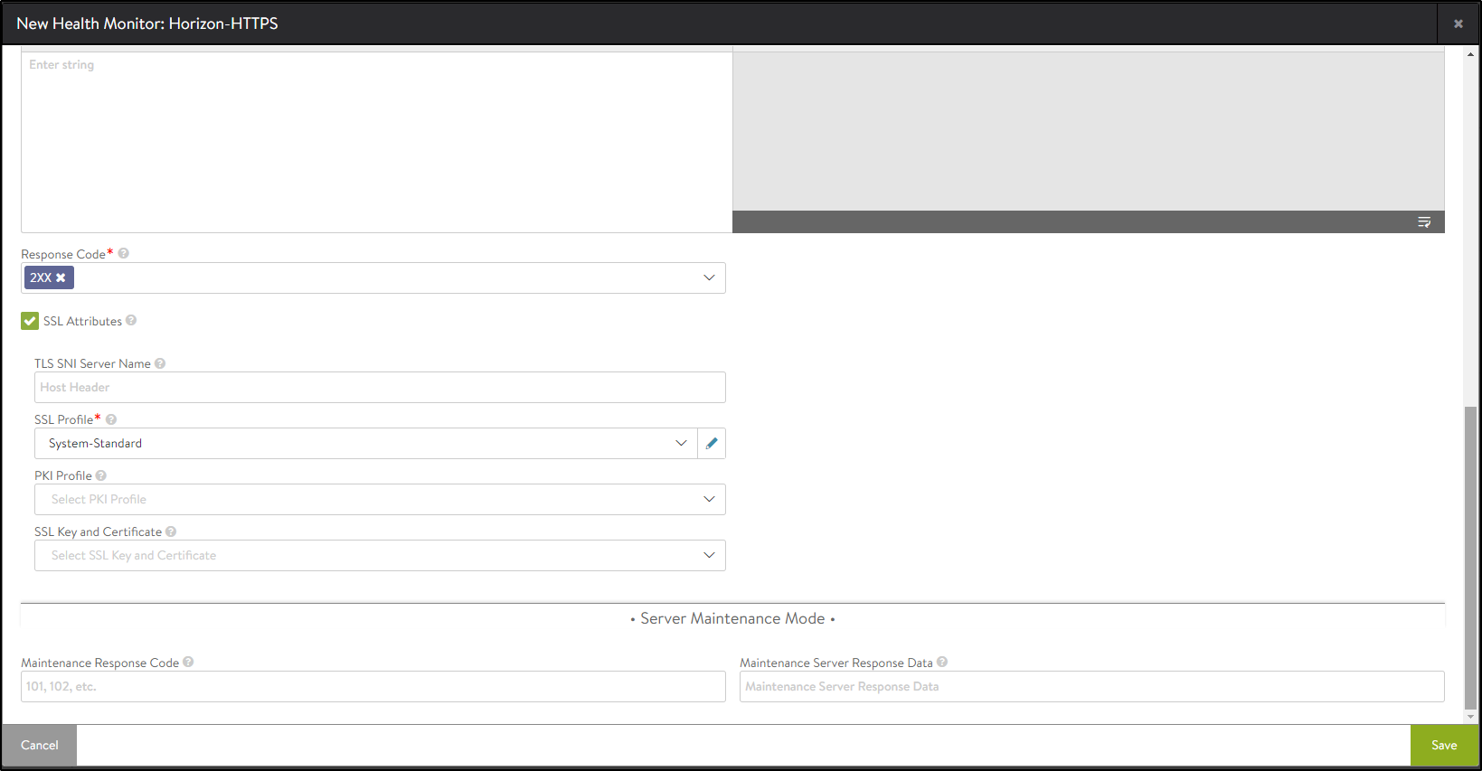
- Click on Save.
Creating SSL Profile for Pool
Create an SSL Profile for the UAG pool with the configuration given below:
- Accepted Versions: 1.2
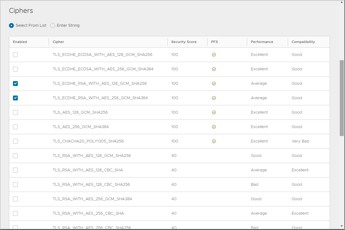
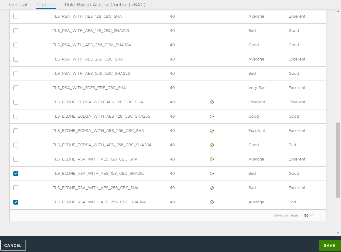
- Cipher List:
TLS_ECDHE_RSA_WITH_AES_128_GCM_SHA256
TLS_ECDHE_RSA_WITH_AES_128_CBC_SHA256
TLS_ECDHE_RSA_WITH_AES_256_GCM_SHA384
TLS_ECDHE_RSA_WITH_AES_256_CBC_SHA384
- Navigate to Templates > SSL/TLS Profile > Create
- Select Application Profile.
- Enter the details as shown below:
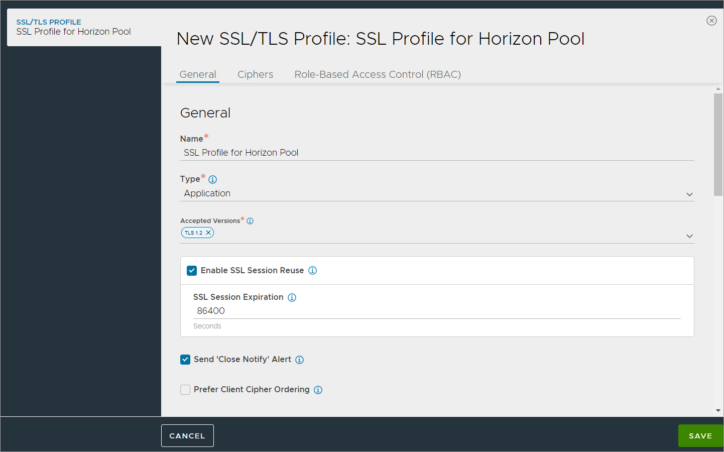
- Click on Save.
Creating Pools
Creating the UAG L7 Pool
To create the pool,
- In Avi Vantage, navigate to Applications > Pools.
- Select the vCenter cloud from the Select Cloud sub-screen.
- Click on Next.
- Click on Create Pool.
- In the New Pool: screen, update the details as shown below:
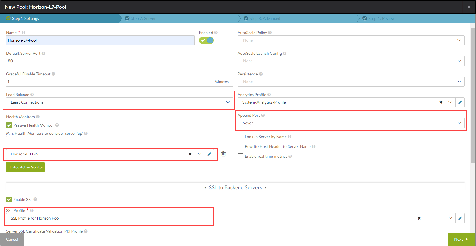
- Click on Next.
- In the Step 2: Servers tab, add the Server IP Address of the UAG servers created earlier and click on Add Server.
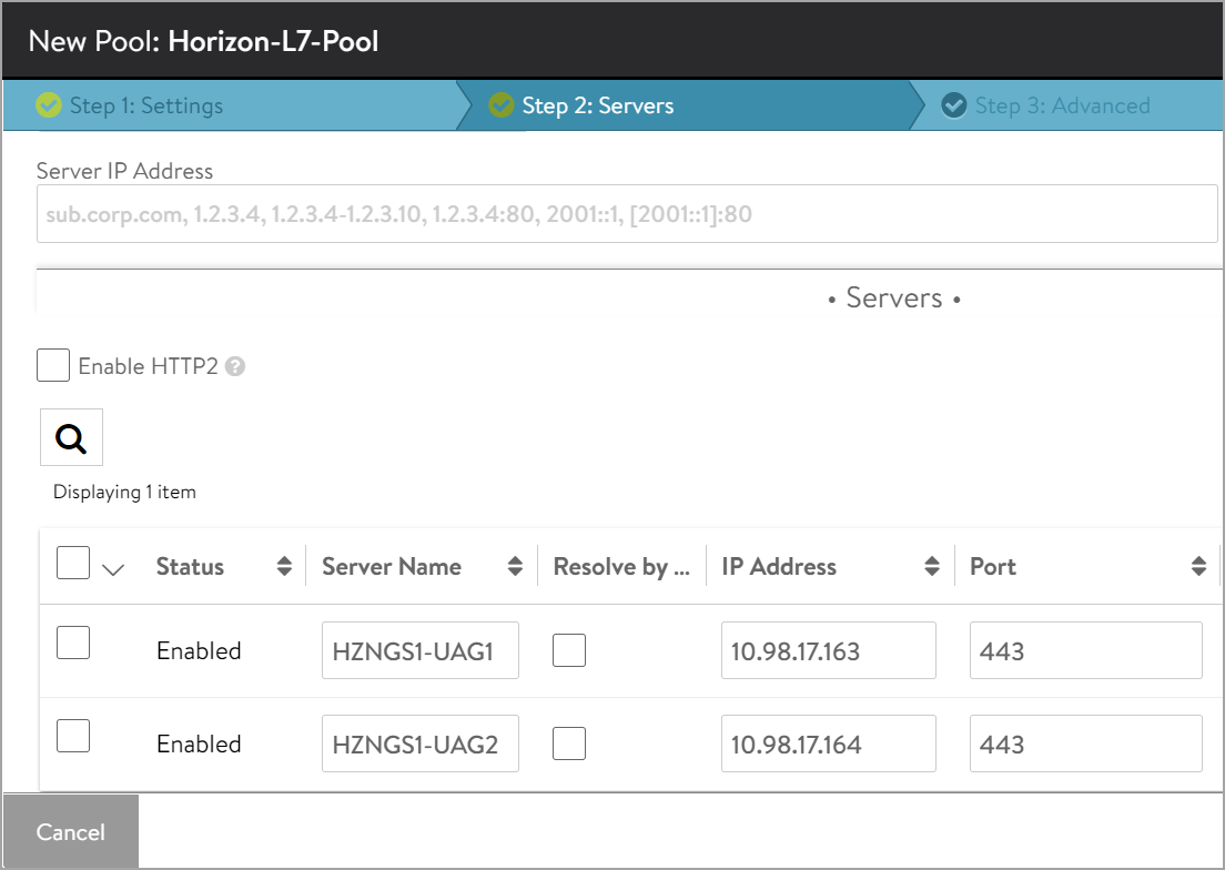
- Click on Next.
- Navigate to Step 3: Advanced tab > Step 4: Review.
- Click on Next and then click on Save.
Creating the UAG L4 Pool
-
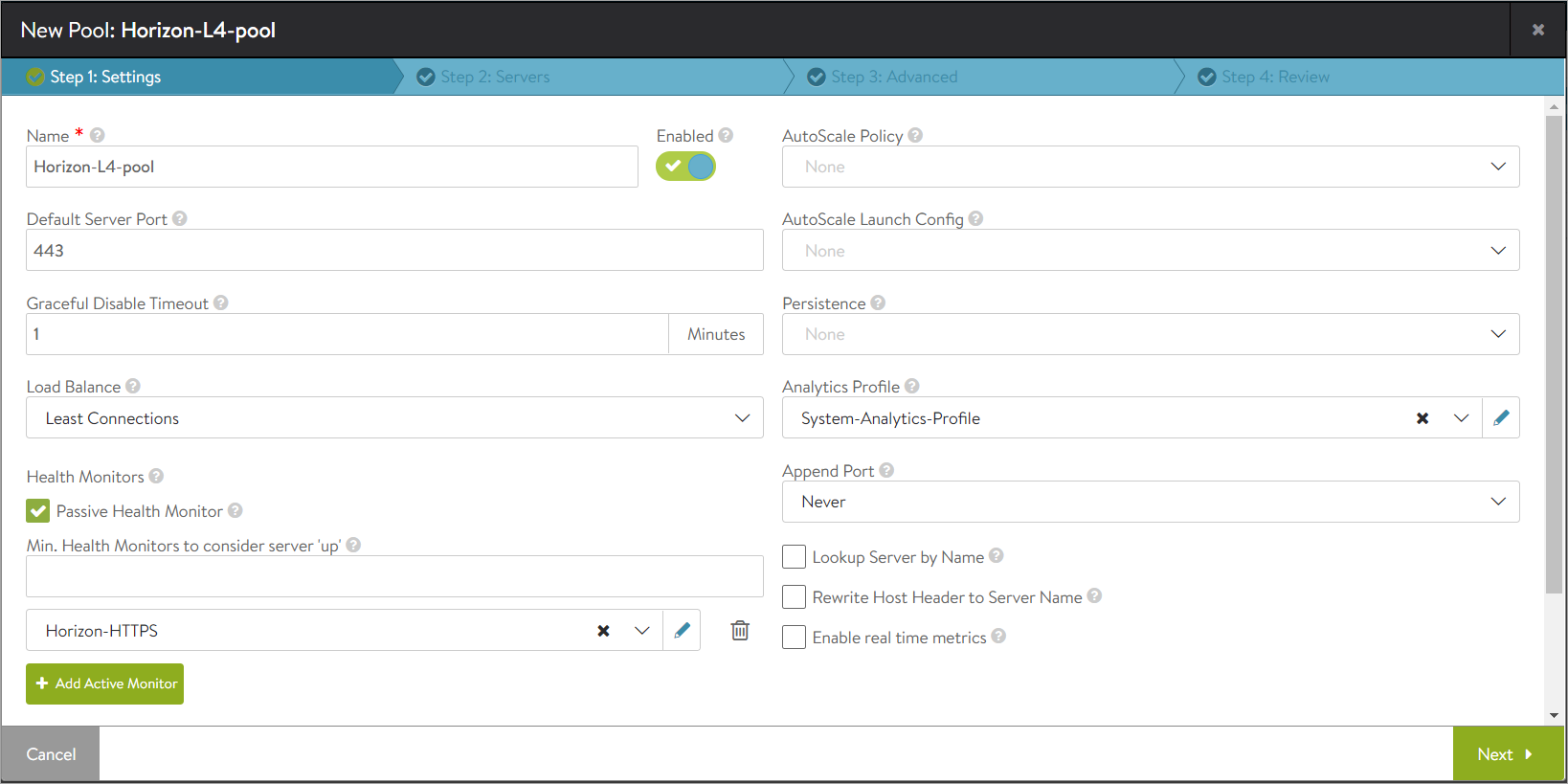
Create a pool with the name Horizon-l4-pool. Ensure that the pool configuration (port , UAG server IP , load balancing algorithm , health monitor etc.) is the same as the Horizon L7 Pool.
-
Under the Step 2: Servers tab, add the Server IP Address of the UAG servers created earlier and click on Add Server.
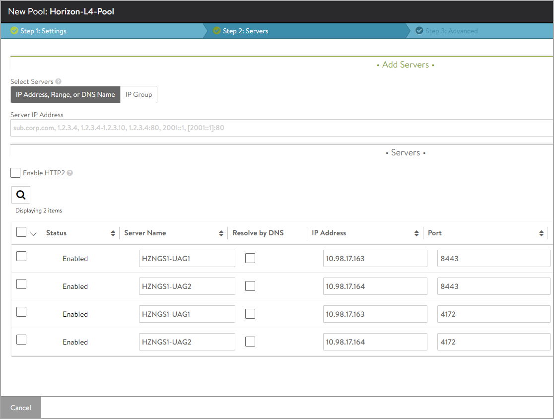
Note: Ensure both the ports are involved for all the UAG servers added here.
- Click Next.
- Click Next and click Save.
Installing the SSL certificate Required for L7 VIP
The SSL connection is being terminated at the Avi virtual service. Therefore, the SSL certificate must be assigned to the virtual service . It is recommended to install a certificate which is signed by a valid certificate authority instead of using self-signed certificates.
Install the certificate in Avi Vantage, and ensure the CA certificate is imported and linked. For information, refer to Import Certificates.
Note: For this set up, a certificate named Horizon_Certificate has been installed.
Disabling Connection Multiplexing
In case of UAG load balancing, disable connection multiplexing for the System-Secure-HTTP-VDI profile.
To disable connection multiplexing,
- Navigate to Templates > Profiles> Application > System-Secure-HTTP-VDI.
- Click on the edit icon.
- Disable the option Connection Multiplexing as shown below:
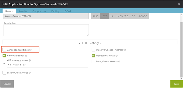
- Click on Save.
Creating SSL Profile for Virtual Service
Create an SSL Profile for the virtual service with the configuration given below:
- Accepted Versions: TLS 1.1, 1.2
- Cipher List:
TLS_ECDHE_ECDSA_WITH_AES_128_GCM_SHA256
TLS_ECDHE_ECDSA_WITH_AES_256_GCM_SHA384
TLS_ECDHE_RSA_WITH_AES_128_GCM_SHA256
TLS_ECDHE_RSA_WITH_AES_256_GCM_SHA384
- Navigate to Templates > SSL/TLS Profile > Create
- Select Application Profile.
- Enter the details as shown below:
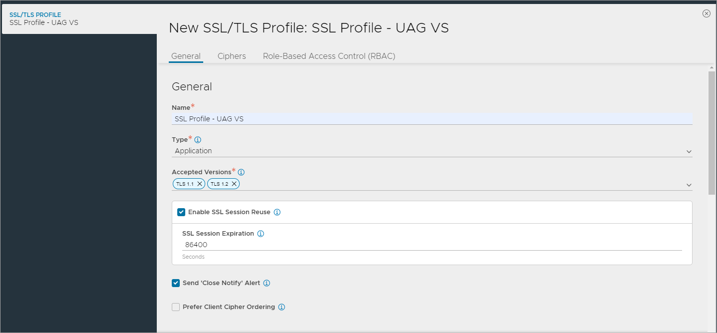
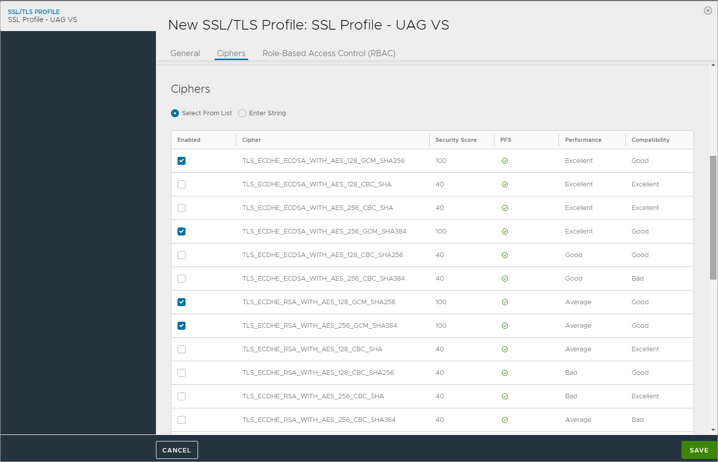
- Click on Save.
Creating L7 Virtual Service and HTTP Request Policies
To create the new L7 virtual service,
- From the Avi UI, navigate to Applications > Virtual Services.
- Click on Create Virtual Service > Advanced Setup.
- Use the
System-Secure-HTTP-VDIas the Application Profile. - Configure the virtual service as shown below:
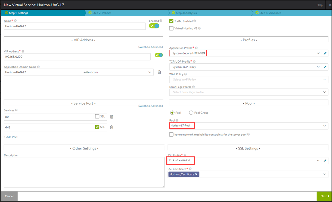
- Click on Next.
- Go to Policies > HTTP Request Policies and add policies as shown below:
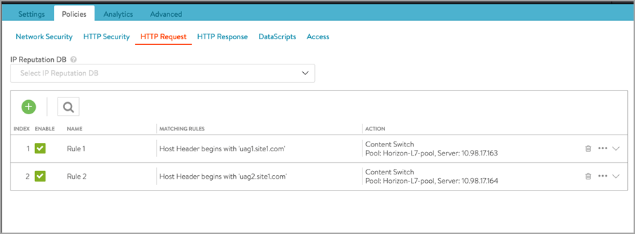 Note: Similarly, create policies on Site 2 as well. Change the host header and IP address of the server accordingly.
 - Click Save.
- Click on Next > Next .
- Click Save.
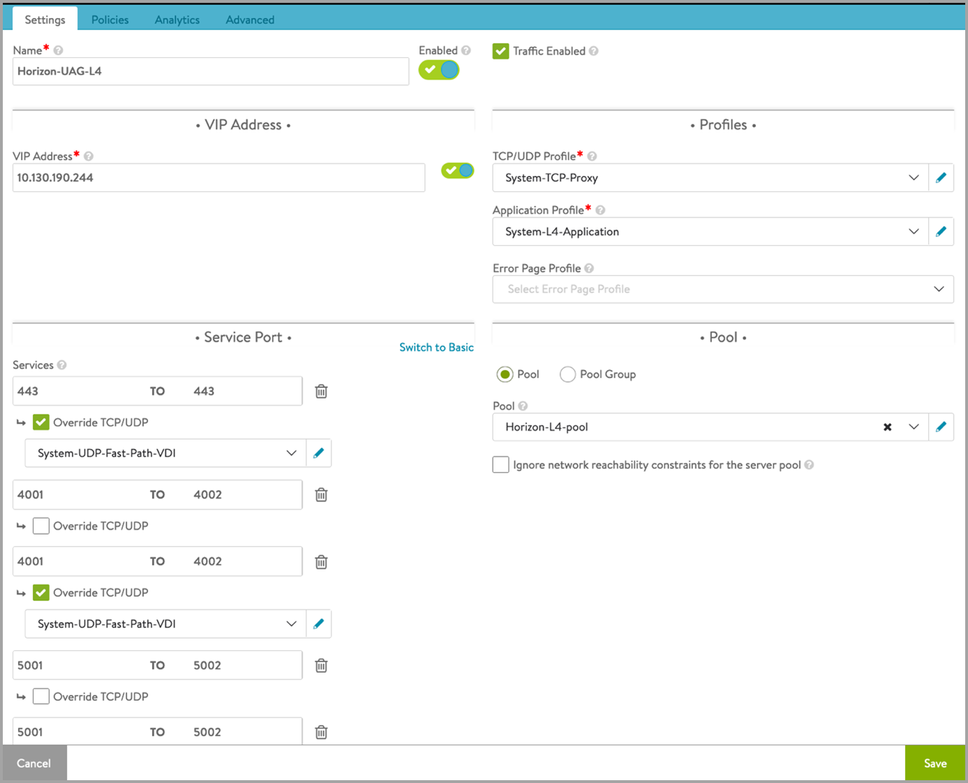
Creating L4 Virtual Service
Create another virtual service which will share the same IP address as that of the L7 VIP. This will make sure that we need only one virtual IP address for both the primary and secondary protocols. L7 virtual service will handle the primary protocol and the tunnel whereas L4 virtual service will handle other secondary protocols. To create an L4 virtual service,
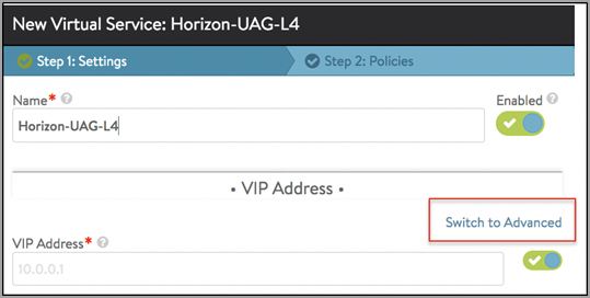
- Click on Create Virtual Service > Advanced Setup.
- In the New Virtual Service screen, click on Switch to Advanced under VIP Address as shown below:
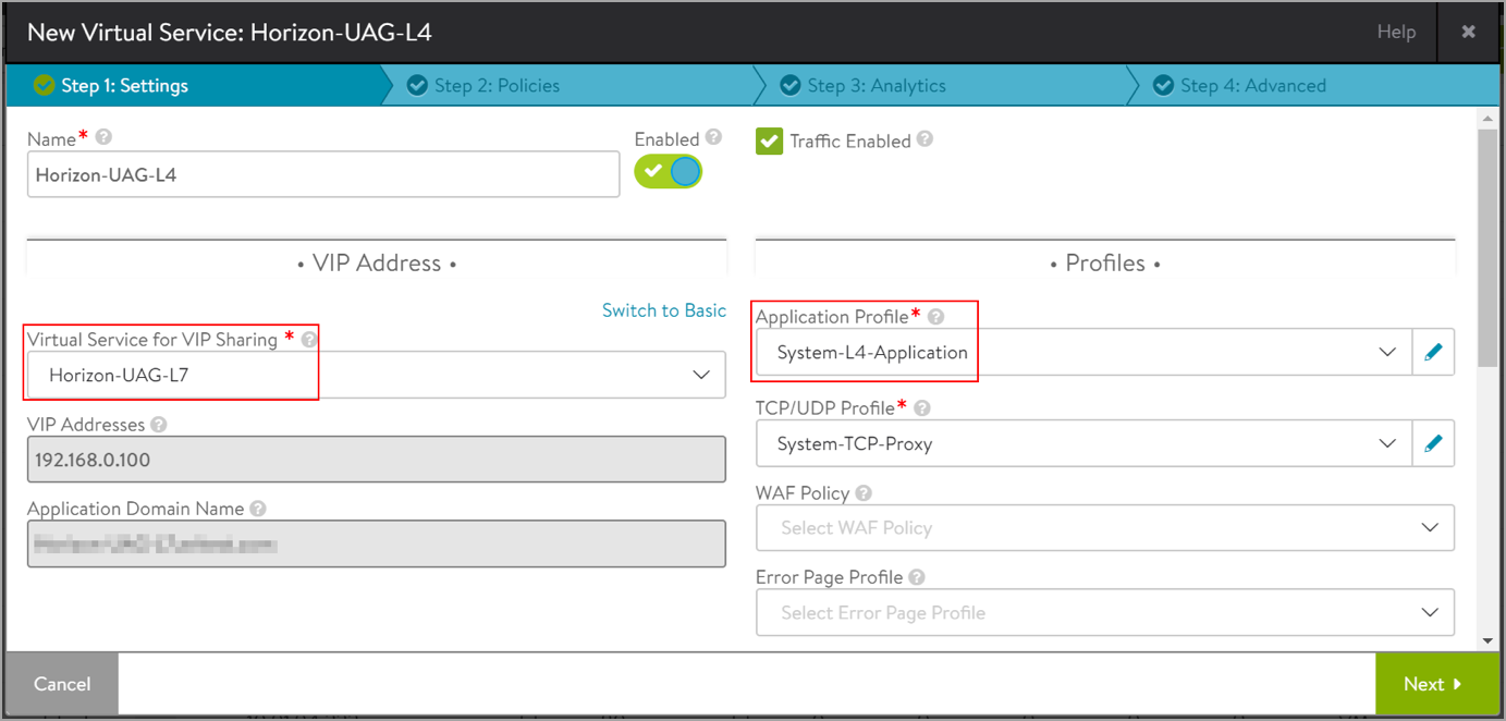
- Select the L7 virtual service that was created as the Virtual Service for VIP Sharing as shown below:
- Under Service Port > Services, click on Switch to Advanced.
- Add the port numbers for the secondary protocols as shown below:
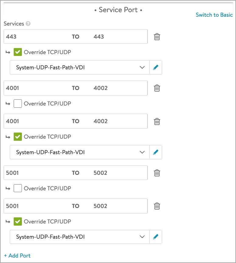 The virtual service is configured as shown below:
Creating the L4 DataScript
- Edit the L4 virtual service which was just created.
- Click on Next.
- Click on DataScript.
- Add the following DataScript for L4 Req Event:
avi_port = avi.vs.port() if avi_port == "4001" then avi.pool.select("L4-pool", "UAG_server1_IP_site1", 8443) elseif avi_port == "4002" then avi.pool.select("L4-pool", "UAG_server2_IP_site1", 8443) elseif avi_port == "5001" then avi.pool.select("L4-pool", "UAG_server1_IP_site1", 4172) elseif avi_port == "5002" then avi.pool.select("L4-pool", "UAG_server2_IP_site1", 4172) endNotes:
- UAG server IP is different on all the sites. Ensure that correct IP addresses are used in data script on both the sites.
- If there more UAG servers, ensure all the server IP:port pairs are added to the L4 pool before creating the DataScript
- In the DataScript pane, bind the L4 pool:
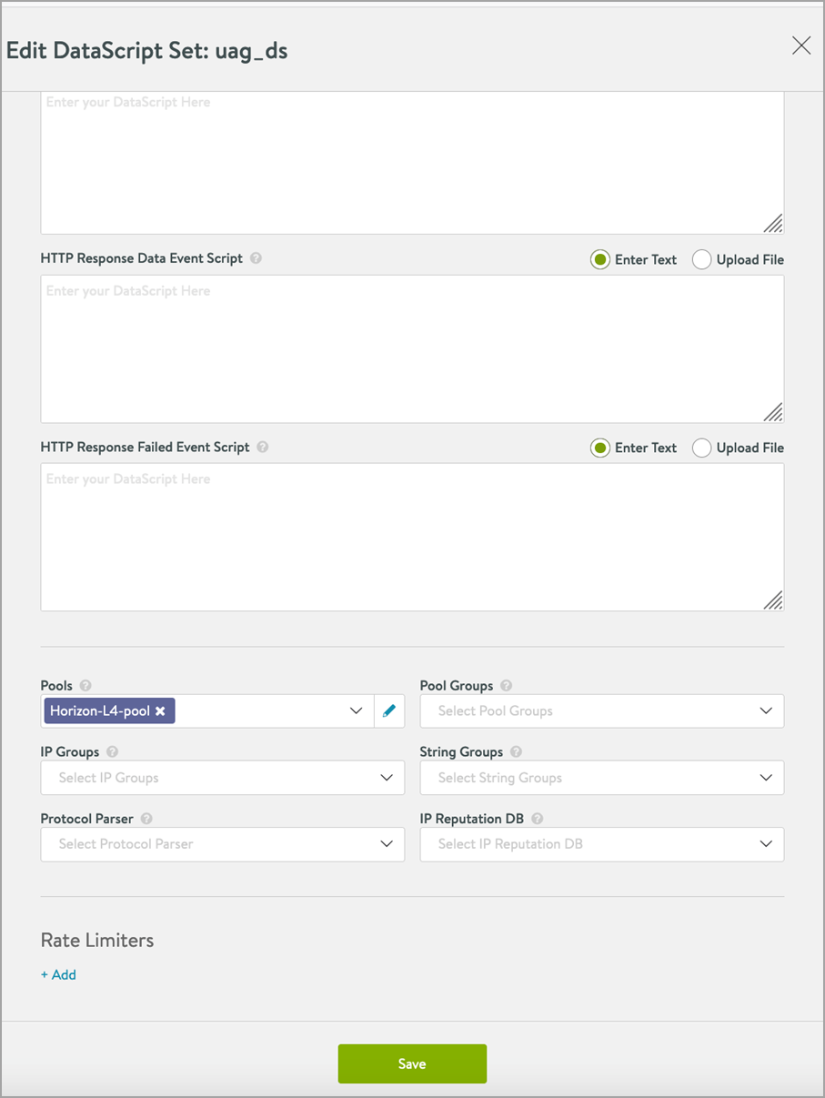
- Click on Save.
Load Balancing Connection Server
Both L4 and L7 virtual services are supported to Load balance traffic to connection servers. However, it is recommended to use L7 virtual services. To know how to use L7 virtual service to load balance traffic to connection servers, refer to the Load Balancing Traffic to Connection Servers article.
The configuration for Site 2 Controller is similar to that of Site 1.
Follow the configuration steps for Site 1 to configure Site 2.
With this, the LB configuration on both the sites is completed.
Avi GSLB Configuration
- Go to the Avi leader site.
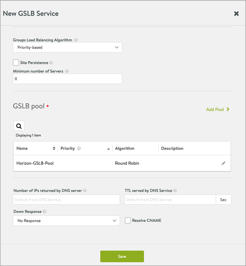
- Navigate to Applications > GSLB services.
- Click Create > Advanced Set up.
- Add the details as shown in the example below:
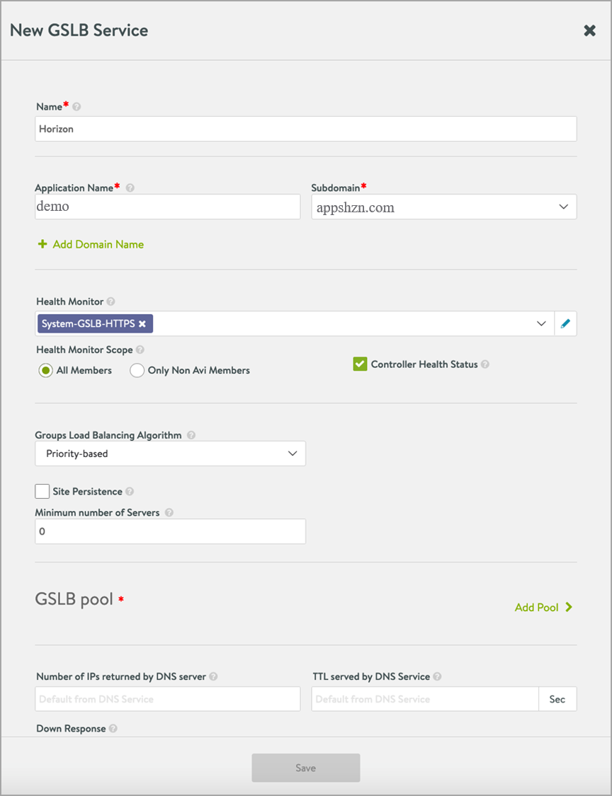
- Click on Add Pool.
- In the New pool screen, add the pool members - UAG L7 VS from both the sites.
- Set the Pool Members Load Balancing Algorithm to Round Robin.
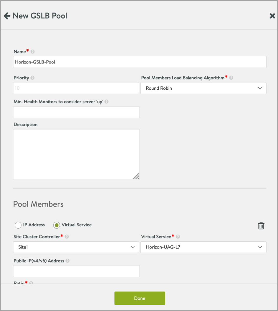
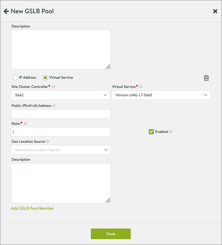
- Click on Save > Save.
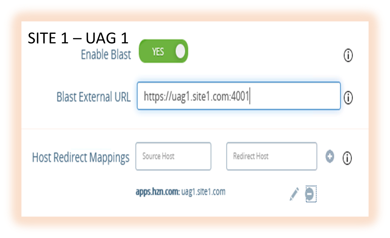
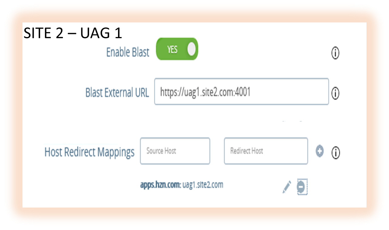
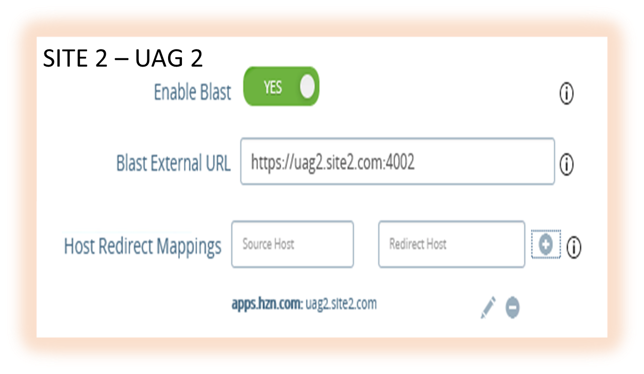
Important Configurations to Check on UAG for This Solution
- Blast URL should point to the UAG hostname/FQDN with the correct port numbers as shown below, for example:
- Site 1 – UAG1 - https://<UAG1 FQDN>:4001/?UDPPort=4001
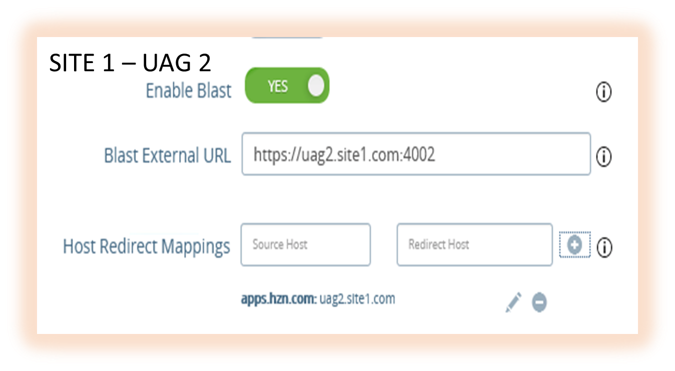
- Site 1 – UAG2 - https://<UAG2 FQDN>:4002/?UDPPort=4002
- Site2 - UAG1 - https://<UAG1 FQDN>:4001/?UDPPort=4001
- Site2 – UAG2 - https://<UAG2 FQDN>:4002/?UDPPort=4002
-
Similarly, PCoIP should point to Avi VIP with correct port numbers.
- Site 1 – UAG1 - https://<Avi VIP IP on site 1>:5001/
- Site 1 – UAG2 - https://<Avi VIP IP on site 1>:5002/
- Site2 - UAG1 - https://<Avi VIP IP on site 2>:5001/
- Site2 – UAG2 - https://<Avi VIP IP on site 2>:5002/
-
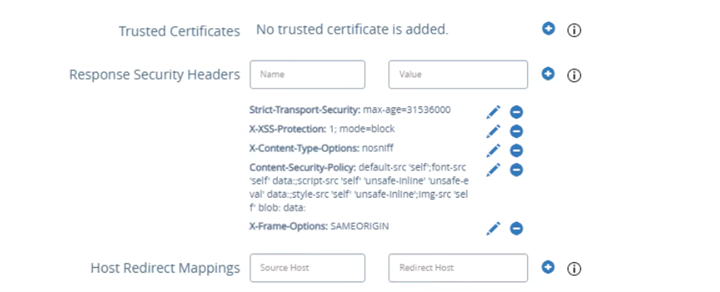
Host Redirect mapping should be configured on all UAGs.
Notes:
- Ensure the following:
- The source host is the GSLB FQDN
- The redirect host is the UAG’s FQDN
- Upload the Avi VS certificate on all the UAG servers
Other Considerations
-
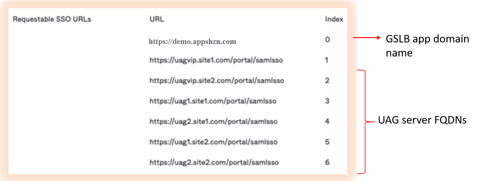
All the host names/FQDNs have to be added in SAML IDP as shown in the example below:
-
Add the SAN certificate to UAG as explained in the Configuring TLS/SSL Certificates for Unified Access Gateway Appliances.
Install the same certificate and key pair on Avi and bind it to the UAG L7 VS.
In some cases, when accessing the VMware Horizon Client, multiple icons for the same site can be displayed as shown below:
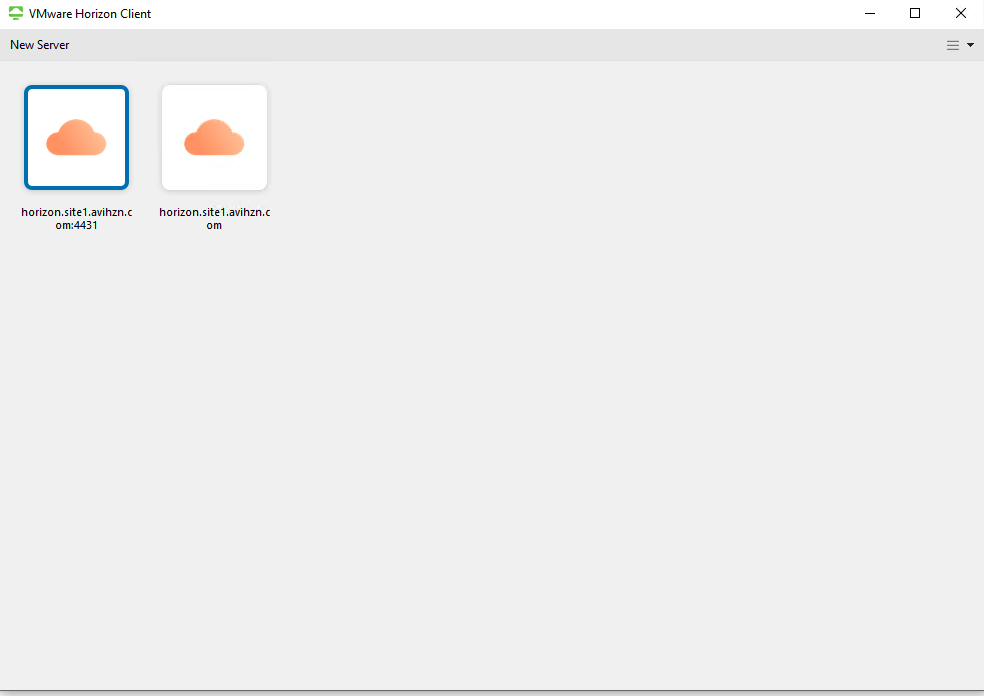
This issue will be resolved in the upcoming releases for Horizon Client.